Chery Tiggo 5 (T21). Manual - part 211


  Index      Chery     Chery Tiggo 5 (T21) - service repair manual 2014 year


Search            


Content   ..  209  210  211  212   ..


Chery Tiggo 5 (T21). Manual - part 211


18–

33

18

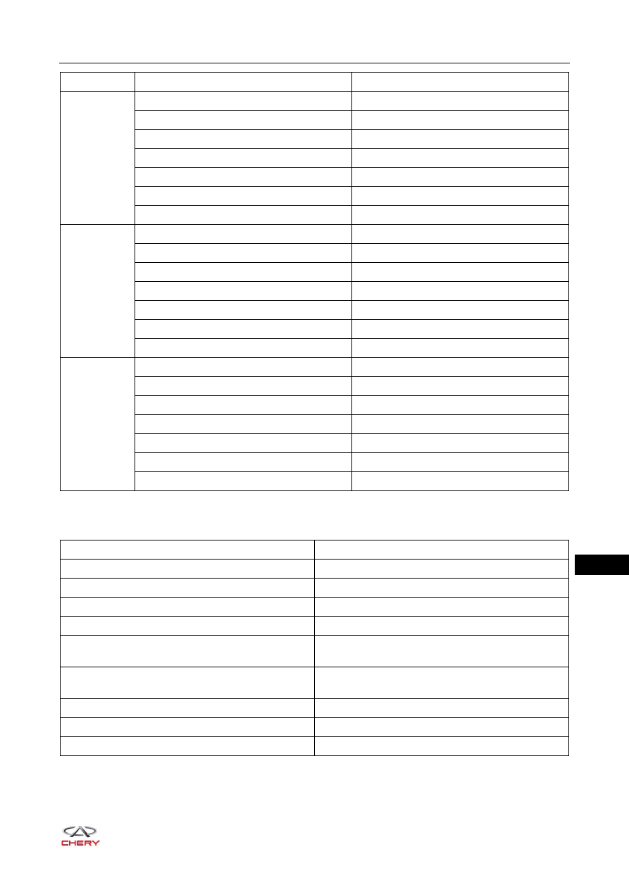
TCU (Transmission Control Unit ) Output Inspection

D

Transmission engagement gear

D gear

Drive pulley pressure

1.1 Bar

Oil temperature

74°C

Driven pulley pressure

9.5 Bar

Driver request

0.00%

Engine torque signal in CAN

1.1%

Engine coolant temperature

95.25°C

L

Transmission engagement gear

Low speed gear

Drive pulley pressure

1.0 Bar

Oil temperature

74°C

Driven pulley pressure

8.2 Bar

Driver request

0.00%

Engine torque signal in CAN

9%

Engine coolant temperature

96°C

M-1

Transmission engagement gear

First gear

Drive pulley pressure

0.9 Bar

Oil temperature

76°C

Driven pulley pressure

9.2 Bar

Driver request

0.00%

Engine torque signal in CAN

11%

Engine coolant temperature

90.75°C

Gear

Data Stream Item

Engine Idle Speed

Data Stream Item

Engine Idle Speed

Clutch duty ratio

99.70%

TCC (torque converter clutch) duty ratio

0.00%

Drive pulley duty ratio

49.241%

Driven pulley duty ratio

76.135%

Transmission engagement gear (transmission 
position)

P gear

Transmission engagement gear (transmission 
working mode)

Common code

Transmission engagement gear (transmission fault)

Non-default

Coolant temperature signal in CAN

93°C

Oil temperature

77°C

18–

34

18

Dynamic Inspection

Speed Inspection

CAN Network

Data Stream Item

Engine Idle Speed

Multi-function switch position

P gear

Engine speed

702.75 rpm

Turbine speed

702 rpm

Vehicle speed

0.00 km/h

Driver request

0.00 NM

Drive pulley pressure

2.063 Bar

Driven pulley pressure

10.076 Bar

Oil temperature

79°C

Engine coolant temperature

92.25°C

Data Stream Item

Engine Idle Speed

Driver request

0.00%

Engine speed

702.75 rpm

Turbine speed

7.2 rpm

Vehicle speed

0.00 km/h

Drive pulley speed

0 rpm

Driven pulley speed

0 rpm

Data Stream Item

Engine Idle Speed

Engine speed

702.75 rpm

Driver request

0.00%

Vehicle speed

0.00 km/h

Engine coolant temperature

90.75°C

Driver request

0.00 NM

Torque converter status

Unlock

18–

35

18

Power Supply and Ground Circuit Test

Power Supply Circuit Test

Power Supply Circuit

ET21180060

IGNITION SEITCH
   ON OR START

BATTERY

TCU

TCU
RELAY 
ERLY12

A4

A2

F15

J2

F16

85

30

86

87

31

28

46

56

3

RL

R

L

L

RL

R

L

EF17

10A

EF19

10A

EF46

20A

A1

A2

A3

A4

A5

A6

A7

A8 A9 A10

J2

J1

F12

F24

F11

F23

F10

F22

F9

F21

F8

F20

F7

F19

F6

F18

F5

F17

F4

F16

F3

F15

F2

F14

F1

F13

29 30 31 32 33 34 35 36 37 38 39 40 41 42

1 2 3 4 5 6 7 8 9 10 11 12 13 14

43 44 45 46 47 48 49 50 51 52 53 54 55 56

15 16 17 18 19 20 21 22 23 24 25 26 27 28

ENGINE 
COMPARTMENT 
FUSE AND 
RELAY BOX

Gr

E-076

W

E-069

B

E-066

B

E-030

E-069

E-076

E-030

E-066

18–

36

18

Check TCU Power Circuit Value

DTC Confirmation Procedure:

Confirm that battery voltage is between 11 and 14 V before performing the following procedures.
 Turn ignition switch to LOCK.
 Connect X-431 3G diagnostic tester (the latest software) to Data Link Connector (DLC), and make it 

communicate with vehicle electronic module by the data network.

 Turn ignition switch to ON.
 Using X-431 3G diagnostic tester to record and clear the DTCs stored in the TCU.
 Turn ignition switch to LOCK and wait for a few seconds.
 Turn ignition switch to ON, and then select "Read Code".
 If DTC is detected, the malfunction indicated by the DTC is current. Go to the diagnosis procedure - Step 1.
 If DTC is not detected, the malfunction indicated by the DTC is intermittent. Please refer to Intermittent 

DTC Troubleshooting.

Diagnosis procedure

Terminal No.

Item

Condition

Value

28

Ignition Switch

Ignition Switch ON

Voltage (11 - 14 V)

46

Ignition Switch

Ignition Switch ON

Voltage (11 - 14 V)

56

Battery Power

-

Voltage (11 - 14 V)

3

Battery Power

-

Voltage (11 - 14 V) 

31

Battery Power

-

Voltage (11 - 14 V) 

1

Check if TCU power fuse EF17, EF19 and EF46 are normal

Replace failed fuse

NG

2

Check if TCU relay 12 operates normally

OK

Replace TCU relay 12

NG

3

Check if ignition switch to fuse box TCU fuse and relay circuit and battery to fuse box TCU 
fuse and relay circuit are normal

OK

Repair or replace failed circuit

NG

OK


Content   ..  209  210  211  212   ..