Chery Tiggo 5 (T21). Manual - part 198


  Index      Chery     Chery Tiggo 5 (T21) - service repair manual 2014 year


Search            


Content   ..  196  197  198  199   ..


Chery Tiggo 5 (T21). Manual - part 198


17–

46

17

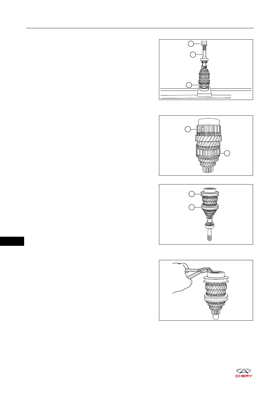
13.Install the input shaft rear bearing.

a. Using a hydraulic press (1), press the input shaft rear 

bearing (3) into the input shaft (2).

14.Install the 5th synchronizer outer race and 3rd-4th synchronizer outer race.

a. Apply transmission oil to the 5th synchronizer 

meshing key and spring (1) and 3rd-4th synchronizer 
meshing key and spring (2), and install them to the 
synchronizer gear hubs.

b. Apply transmission oil to 5th synchronizer outer race 

(1) and 3rd-4th synchronizer outer race (2), and install 
them to the input shaft.

15.Install the input shaft rear bearing snap ring.

a. Using snap spring calipers, install the rear bearing 

snap ring.

3

2

1

RT21170760

1

2

RT21170770

1

2

RT21170780

RT21170790

17–

47

17

Inspection

1. Using a feeler gauge, measure clearance between 3rd 

drive gear and synchronizer ring.
Standard value: 1.35 mm
Limit value: 1.100 - 1.600 mm

2. Using a feeler gauge, measure clearance between 4th 

drive gear and synchronizer ring.
Standard value: 1.35 mm
Limit value: 1.100 - 1.600 mm

3. Using a feeler gauge, measure clearance between 2nd 

drive gear and 3rd drive gear.
Standard value: 0.65 mm
Limit value: 0.45 - 0.85 mm

CAUTION

 Check gears on the input shaft for smooth rotation after installation.
 Check engagement of gears on the input shaft for looseness or sticking.

RT21173040

RT21173041

RT21173042

17–

48

17

Output Shaft

Disassembly

1. Remove the output shaft (

See page 17-22

).

2. Remove the output shaft rear bearing.

a. Using a special tool (1), secure the output shaft rear 

bearing (2).

b. Using a hydraulic press (1), press the output shaft 

rear bearing (3) out of output shaft (2), and remove 
the output shaft rear bearing.

3. Remove the 5th driven gear and 4th driven gear.

a. Using snap spring calipers (1), remove the snap ring.

b. Using a special tool (1), secure the 5th and 4th driven 

gear set (2).

1

2

RT21170800

3

1

2

RT21170810

1

RT21170820

2

1

RT21170830

17–

49

17

c. Using a hydraulic press (1), press the 5th and 4th 

driven gear set (3) out of output shaft (2), and remove 
the 5th driven gear and 4th driven gear.

4. Remove the gear shaft bushing.

a. Remove the gear shaft bushing (1) from output shaft.

5. Remove the 2nd driven gear and 3rd driven gear.

a. Using a special tool (1), secure the 2nd driven gear 

(2).

b. Using a hydraulic press (1), press the 2nd and 3rd 

driven gears (3) out of output shaft (2), and remove 
the 2nd driven gear and 3rd driven gear.

RT21170840

1

2

3

1

RT21170850

1

2

RT21170860

1

3

2

RT21170870


Content   ..  196  197  198  199   ..