Chery Tiggo 5 (T21). Manual - part 154


  Index      Chery     Chery Tiggo 5 (T21) - service repair manual 2014 year


Search            


Content   ..  152  153  154  155   ..


Chery Tiggo 5 (T21). Manual - part 154


12–

17

12

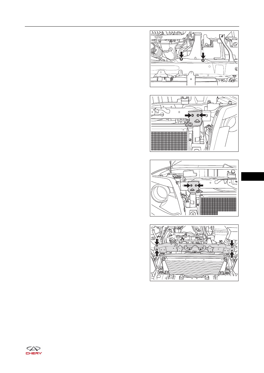
c. Remove 2 coupling bolts (arrow) between air 

induction pipe assembly and tank upper crossmember 
assembly.

(Tightening torque: 7 ± 1 N·m)

d. Remove 2 fixing bolts (arrow) from radiator left tension 

plate, and remove the radiator left tension plate.

(Tightening torque: 7 ± 1 N·m)

e. Remove 2 fixing bolts (arrow) from radiator right 

tension plate, and remove the radiator right tension 
plate.

(Tightening torque: 7 ± 1 N·m)

f. Remove 4 fixing bolts (arrow) from tank upper 

crossmember assembly.

(Tightening torque: 7 ± 1 N·m)

g. Remove the tank upper crossmember assembly.

Installation

Installation is in the reverse order of removal.

RT21120036

RT21120033

RT21120034

RT21120035

12–

18

12

Expansion Tank

Removal

1. Turn off all the electrical equipment and ignition switch.
2. Drain the coolant (

See page 12-13

).

3. Remove the expansion tank.

a. Loosen the elastic clamp (1) and disconnect the 

connection between expansion tank and discharge 
pipe I.

b. Loosen the elastic clamp (2) and disconnect the 

connection between expansion tank and discharge 
pipe II.

c. Loosen the elastic clamp (3) and disconnect the 

connection between expansion tank and expansion 
tank outlet hose.

d. Remove 2 fixing bolts (arrow) from expansion tank.

(Tightening torque: 7 ± 1 N·m)

e. Remove the expansion tank from expansion tank bracket.

Installation

Installation is in the reverse order of removal.

WARNING

 Always make sure engine is cold before operating cooling system.
 Never open expansion tank cap or remove drain cock plug when engine is operating or cooling system 

overheats. The overheated engine coolant and steam with high-pressure may flow out and cause 
serious personal injury.

 If your body contacts coolant accidentally, clean it with water immediately. If it is serious, please go to 

hospital.

CAUTION

 Be sure to wear necessary safety equipment to prevent accidents when repairing.
 Try to prevent body paint surface from being scratched during removal and installation.

3

2

1

RT21120080

CAUTION

 Check that coolant has been added to the specified level after installation.

12–

19

12

Thermostat

Removal

1. Turn off all the electrical equipment and ignition switch.
2. Disconnect the negative battery cable.
3. Remove the engine trim cover assembly (

See page 10-10

).

4. Remove the air induction pipe assembly (

See page 10-16

).

5. Drain the coolant (

See page 12-13

).

6. Remove the canister solenoid valve bracket.

a. Move away the canister solenoid valve from the bracket.
b. Remove 2 fixing bolts (arrow) from activated charcoal 

canister solenoid valve bracket, and remove the 
activated charcoal canister solenoid valve bracket.

(Tightening torque: 7 ± 1 N·m)

7. Remove the thermostat housing.

a. Loosen the elastic clamp (arrow) and disconnect the 

connection between engine outlet hose and 
thermostat housing.

WARNING

 Always make sure engine is cold before operating cooling system.
 Never open expansion tank cap or remove drain cock plug when engine is operating or cooling system 

overheats. The overheated engine coolant and steam with high-pressure may flow out and cause 
serious personal injury.

 If your body contacts coolant accidentally, clean it with water immediately. If it is serious, please go to 

hospital.

CAUTION

 Be sure to wear necessary safety equipment to prevent accidents when repairing.
 Try to prevent body paint surface from being scratched during removal and installation.

RT21090040

RT21120090

12–

20

12

b. Remove 4 fixing bolts (arrow) from thermostat 

housing.

(Tightening torque: 8 + 3 N·m)

c. Remove the thermostat housing.

8. Remove the thermostat.

a. Take out the thermostat (arrow) from thermostat seat.

Inspection

1. As show in the illustration, check if the protrusion (2) of 

thermostat grommet and chock (1) of thermostat are 
installed at an angle of 180°.
If the result is not as specified, adjust the thermostat 
grommet to the specified position or replace the 
thermostat with a new one.

2. Check the opening temperature and maximum lift of 

thermostat.

HINT:
Valve opening temperature is engraved in the thermostat.

RT21120100

RT21120110

RT21120120

1

2

RT21120130

87

0

C

B

3

87

0

C


Content   ..  152  153  154  155   ..