Chery Tiggo 5 (T21). Manual - part 128


  Index      Chery     Chery Tiggo 5 (T21) - service repair manual 2014 year


Search            


Content   ..  126  127  128  129   ..


Chery Tiggo 5 (T21). Manual - part 128


07–

98

07

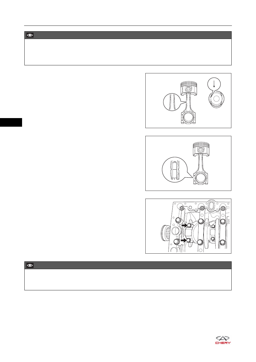
7. Install the connecting rod bearing cap.

HINT:
The direction of the number on one side of connecting 
rod is the same as that of the number on the connecting 
rod bearing cap. These numbers are cylinder numbers 
indicating at which cylinder are located. For example, 
number 3 indicates that the mounting position is at No.3 
cylinder.

a. Install the connecting rod bearing cap in place, and 

screw the connecting rod bearing cap fixing bolts 
(arrow) by hands, then tighten the connecting rod 
bearing cap fixing bolts in two steps.

(Tightening torque: 1st step: tighten to 25 ± 3 N·m; 
2nd step: retighten for 90° ± 5°)

8. Other assembly is in the reverse order of disassembly.

CAUTION

 Pay attention to the front marks of piston and connecting rod during assembly without being reversed. 

Install them with the side stamped with letter "481HK" on the connecting rod and piston top arrow facing 
toward timing belt side as shown in the illustration.

481HK

RT21071270

481HK

481HK

RT21071280

3

3

RT21070950

CAUTION

 Apply a small amount of engine lubricant to the connecting rod, connecting rod bearing cap and thread 

joint surface.

08–

3

08

SQR484F FUEL SUPPLY SYSTEM

GENERAL INFORMATION

Description

RT21080010

×3

×5

7

4

9

1

2

3

5

6

8

17

16

13

15

14

11

12

10

08–

4

08

Engine fuel supply system provides a certain amount and concentration of combustible air-fuel mixture and 
supplies it to cylinders according to the requirements under various operating conditions of engine. Fuel 
supply system consists of fuel tank assembly, electric fuel pump assembly, fuel filter assembly, delivery pipe, 
fuel rail and injectors, and is used for fuel storage, filtration, delivery and injection.
Function of fuel supply system is to provide gasoline with sufficient pressure to fuel injectors by using electric 
fuel pump assembly, and the injector injects a certain amount of gasoline to the top of intake valve in intake 
manifold in accordance with control signals from ECM.

Specifications

Torque Specifications

Fuel Pressure Specifications

1 - Fuel Pump Pressure Cap

2 - Electric Fuel Pump Assembly

3 - Fuel Tank Seal Ring

4 - Fuel Level Sensor

5 - Fuel Tank Cap Assembly

6 - Filler Tube Assembly

7 - Fuel Breather Hose

8 - Fuel Filler Hose

9 - Fuel Tank

10 - Inlet Pipe I

11 - Inlet and Return Pipe Assembly

12 - Fuel Filter Assembly

13 - Fuel Tank Fixing Strap I

14 - Fuel Tank Fixing Strap II

15 - Fuel Tank Fixing Strap III

16 - Inlet Pipe II

17 - Fuel Rail Injector Assembly

Description

Torque (N·m)

Fuel Filter Ground Wire Fixing Nut

7 ± 1

Fuel Filter Bracket Fixing Screw

3.5 ± 0.5

Fuel Tank Pressure Cap

75 ± 5

Coupling Bolt Between Filler Tube Assembly and
Body

22 ± 2

Filler Tube Assembly Fixing Nut

7 ± 1

Fuel Tank Fixing Strap Fixing Bolt

25 ± 3

Fuel Level Sensor Fixing Screw

5 ± 1

Fuel Rail Fixing Bolt

8 + 3

Worm Clamp

3.5 ± 0.5

SQR484F

Pressure (kPa)

Fuel Pressure on Fuel Rail - Key (ON)

400

Fuel Pressure on Fuel Rail - Engine Idling

400

Fuel Pressure on Fuel Rail - Key (LOCK)

400


Content   ..  126  127  128  129   ..