Chery Tiggo 5 (T21). Manual - part 96
06–
226
06
a. Measure compression of misfiring cylinder (
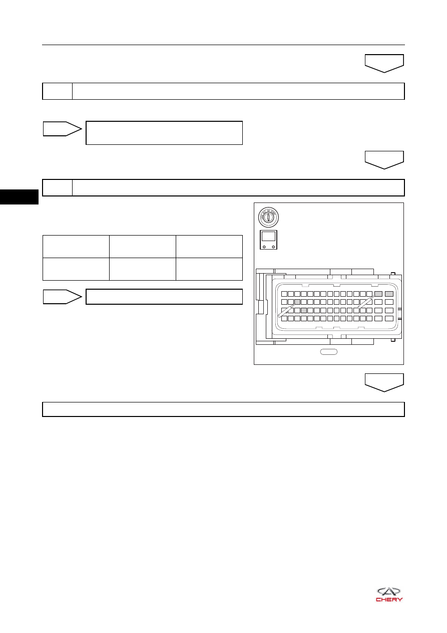
a. Disconnect ECM connector E-033.
b. Turn ignition switch to ON and check ECM connector
terminals.
7
Check pressure of cylinder
OK
Check engine to confirm cause of low
compression
NG
8
Check ECM power supply and ground
OK
E-033
49 50 51
63
64
15
16
31
32
47
48
33 34 35
17 18 19
1 2 3
52 53 54 55 56 57 58 59 60 61 62
36 37 38 39 40 41 42 43 44 45 46
20 21 22 23 24 25 26 27 28 29 30
4 5 6 7 8 9 10 11 12 13 14
-
+
V
RT21065069
Multimeter
Connection
Condition
Specified
Condition
E-033 (35, 20) -
E-033 (63 or 64)
Ignition switch ON
11 to 14 V
Repair or replace related wire harness
NG
Go to Diagnostic Help
OK