Chery Tiggo. Manual - part 439


  Index      Chery     Chery Tiggo - service repair manual 2009 year


Search            


Content   ..  437  438  439  440   ..


Chery Tiggo. Manual - part 439


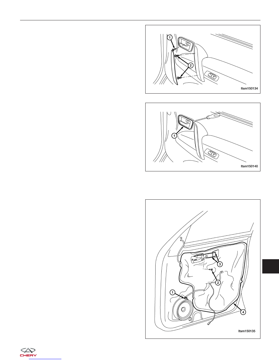
3. Remove the inner door handle mounting screw (1).

4. Remove the pull handle mounting screws (2).

5. Using a small trim stick, remove the inner door

handle trim bezel (1).

6. Carefully pry the door trim panel clips from the door.

7. Disconnect the power window switch and the door lamp electrical connector.

8. Remove the door trim panel.

9. Disconnect the speaker connector (1).

10. Remove the inner door handle assembly mounting

screw (2).

11. Disconnect the inner door handle cables (3).

12. Remove the protective film (4).

DOORS

LTSM150134

LTSM150140

LTSM150135

15


13. Temporarily connect the power window switch.

14. Turn the ignition switch on and use the power window switch to move the front door glass to a position so the

door glass bolts can be removed.

15. Turn the ignition switch off and disconnect the power window switch.

16. Remove the two door glass mounting bolts (1).

(Tighten: Door glass mounting bolts to 11 N·m)

NOTE: Properly support the door glass when
removing the mounting bolts. The door glass may
drop and be damaged.

17. Remove the door glass weatherstrip (1).

18. Lift the door glass and remove the door glass from

the door.

NOTE: Take care not to damage the door glass.

19. Disconnect the power window motor electrical con-

nector.

20. Remove the six power window regulator mounting

bolts (1).
(Tighten: Power window regulator mounting bolts to
11 N·m)

21. Carefully remove the power window regulator.

22. Remove the power window motor from the regulator.

23. Remove three door lock assembly retaining bolts.

(Tighten: Door lock assembly retaining bolts to 9 ± 1 N·m)

DOORS

LTSM150116

LTSM150137

LTSM150117


24. Remove the internal unlock cable (1) and lock

cable (2).

25. Remove the lock buckle with screwdriver.

(Tighten: Lock buckle screws to 12 ± 2 N·m)

26. Remove the front door outside handle.

27. Remove the front door panel and then the protec-

tive film.

28. Pry up on the cover (1) of the outside handle.

29. Remove the mounting bolts with hexagon spline

wrench.

DOORS

LTSM150098

LTSM150114

15


30. Detach the lock from the linkage rod, remove the

lock and the cover of left front door.

31. Remove the outside handle.

Assembly

Assemble is in the reverse order of disassembly

Front Door Adjustment

1. Adjust the door gap with a spacer gauge.

• The gap of the upper section between the front door and the back door should be 5.5 ± 0.7 mm

• The gap of the outboard side should be 5.5 ± 0.7 mm

• The gap between the front door and pole A should be 6.5 ± 1 mm

• The gap of upper section between front door and back door should be 5.5 ± 0.7 mm

• The gap between the front/back door and the doorsill should be 6 ± 1 mm

• The overall levelness when measured with a magnet should be 0-0.5 mm

2. Install the bolts (Part Number: T11-6101103, 2 pcs both upper and lower) into the body for 2-3 turns, tighten with

pneumatic wrench. Torque: 35 ± 3 N·m.

Check for the following after repair:
• Any scratches from reassembly

• Whether the bolts and nuts are assembled properly

• Whether the bolts and nuts are properly tightened

• Whether the gap and levelness between front door and back door is within the specifications

• Whether the edge height is 0-0.5 mm.

Replacing Front Door Hinge

1. Remove the front fender to gain access to the door hinge (See Fender Removal & Installation in Section 15

Body & Accessories).

2. Support the door.

3. Remove the four retaining bolts from the upper and lower hinges, and then remove the hinges.

DOORS

LTSM150120


Content   ..  437  438  439  440   ..