Chery Tiggo. Manual - part 429
4.
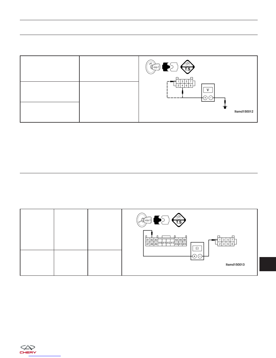
CHECK IMMOBILIZER CONTROL MODULE POWER SUPPLY
• Turn ignition switch on.
• Check if voltage is present on the Immobilizer control module connector C-025, pin 4,1 and ground.
IMMOBILIZER CONTROL
MODULE TERMINAL
GROUND
1
Ground
4
Is 12 V present?
Yes
>>
Replace and program the Immobilizer control module. Refer to DTC B3077 Diagnostic Procedure.
No
>>
For DTC B3050, go to the next step.
For DTC B3053, go to the step 6.
5.
CHECK IMMOBILIZER CONTROL MODULE POWER SUPPLY CIRCUIT
• Turn ignition switch off.
• Disconnect the negative battery cable.
• Disconnect the body fuse and relay box electrical connector A.
• Check harness continuity between the following terminals:
• Continuity should exist.
BODY FUSE
AND RELAY
BOX
TERMINAL
IMMOBILIZER
CONTROL
MODULE
TERMINAL
CONTINUITY
A2
1
Yes
DIAGNOSIS & TESTING
15