Chery Tiggo. Manual - part 371


  Index      Chery     Chery Tiggo - service repair manual 2009 year


Search            


Content   ..  369  370  371  372   ..


Chery Tiggo. Manual - part 371


Parking Brake Shoes

Removal & Installation

1. Raise and support the vehicle.

2. Remove the rear wheel mounting nuts and both rear tire and wheel assemblies.

(Tighten: Wheel mounting nuts to 110 N·m)

3. Access and remove rear brake rotor (See Rear

Brake Rotor Removal & Installation in Section 12
Brakes).

4. Turn the brake shoe adjuster wheel until the

adjuster is at shortest length.

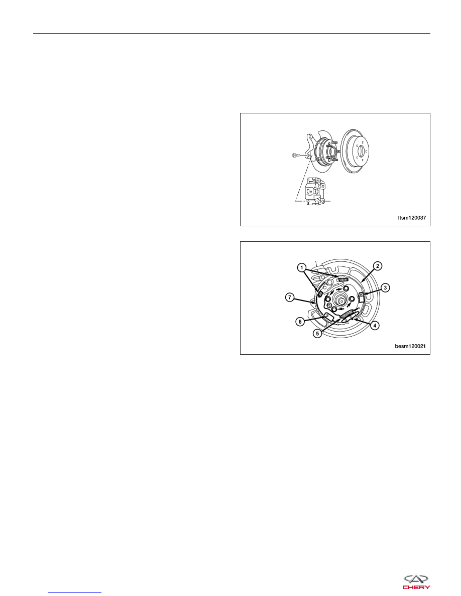
5. Remove the brake shoe hold-down springs (3) and

pins (6). Rotate the pins 90° to disengage.

6. Remove the parking brake cable from the arm on

the rear parking brake shoe.

7. Remove the brake shoes (2, 7), adjuster (4) and

lower return spring (5) as an assembly from the
support plate.

8. Remove the lower return spring (5) and adjuster

(4) from the shoes (2, 7).

9. Remove the parking brake shoes.

10. Installation is in the reverse order of removal.

ON-VEHICLE SERVICE

LTSM120037

BESM120021


Installation Notes:
• Perform the following to measure and adjust parking brake shoes:

1. Using a brake measuring gauge or equivalent, measure the inside diameter of parking brake drum (1).
2. Place the brake measuring gauge over the
parking brake shoes at their widest point.

3. Using the adjuster wheel, adjust the parking brake shoes until the linings on both parking brake shoes just
touch the jaws on the brake measuring gauge.

• After installation, adjust the parking brake cable as

necessary (See Parking Brake Adjustment in Sec-
tion 12 Brakes).

BRAKE SHOES

NEW THICKNESS

MINIMUM THICKNESS

Rear Shoes

2.5 mm

1.5 mm

ON-VEHICLE SERVICE

BESM120024

LTSM120039

12


HEATING & AIR CONDITIONING

13

CONTENTS

page

Manual Temperature Control . . . . . . . . . . . . . . . . . . . . . . . . . . . . . . . . . . . . . . . . . . . . . . . . . . . . . . . . . . . 13-1

System Controls . . . . . . . . . . . . . . . . . . . . . . . . . . . . . . . . . . . . . . . . . . . . . . . . . . . . . . . . . . . . . . . . . . . . 13-18

Air Distribution . . . . . . . . . . . . . . . . . . . . . . . . . . . . . . . . . . . . . . . . . . . . . . . . . . . . . . . . . . . . . . . . . . . . . 13-25

System Plumbing . . . . . . . . . . . . . . . . . . . . . . . . . . . . . . . . . . . . . . . . . . . . . . . . . . . . . . . . . . . . . . . . . . . 13-32

MANUAL TEMPERATURE CONTROL

GENERAL INFORMATION

13-2

Description

13-2

Operation

13-4

Specifications

13-4

Special Tools

13-5

Electrical Schematics

13-6

DIAGNOSIS & TESTING

13-12

A/C System Performance

13-12

Heater Performance

13-14

ON-VEHICLE SERVICE

13-15

Manual Temperature Control Module

13-15

Removal & Installation

13-15

Blower Motor Resistor

13-16

Removal & Installation

13-16

13


GENERAL INFORMATION

Description

This vehicle is equipped with a common HVAC housing assembly. The system combines air conditioning, heating,
and ventilating capabilities in a single unit housing mounted under the instrument panel. The driver can choose the
following functions from HVAC control panel:

• The inside temperature

• The speed of the blower

• Five different modes of operation

• A/C compressor clutch operation

• Recirculation door position

NOTE :
To maintain the performance level of the heating, ventilation and air conditioning (HVAC) system, the engine cooling
system must be properly maintained. Any obstructions in front of the radiator or A/C condenser will reduce the per-
formance of the A/C and engine cooling systems.


Content   ..  369  370  371  372   ..