Chery Tiggo. Manual - part 331


  Index      Chery     Chery Tiggo - service repair manual 2009 year


Search            


Content   ..  329  330  331  332   ..


Chery Tiggo. Manual - part 331


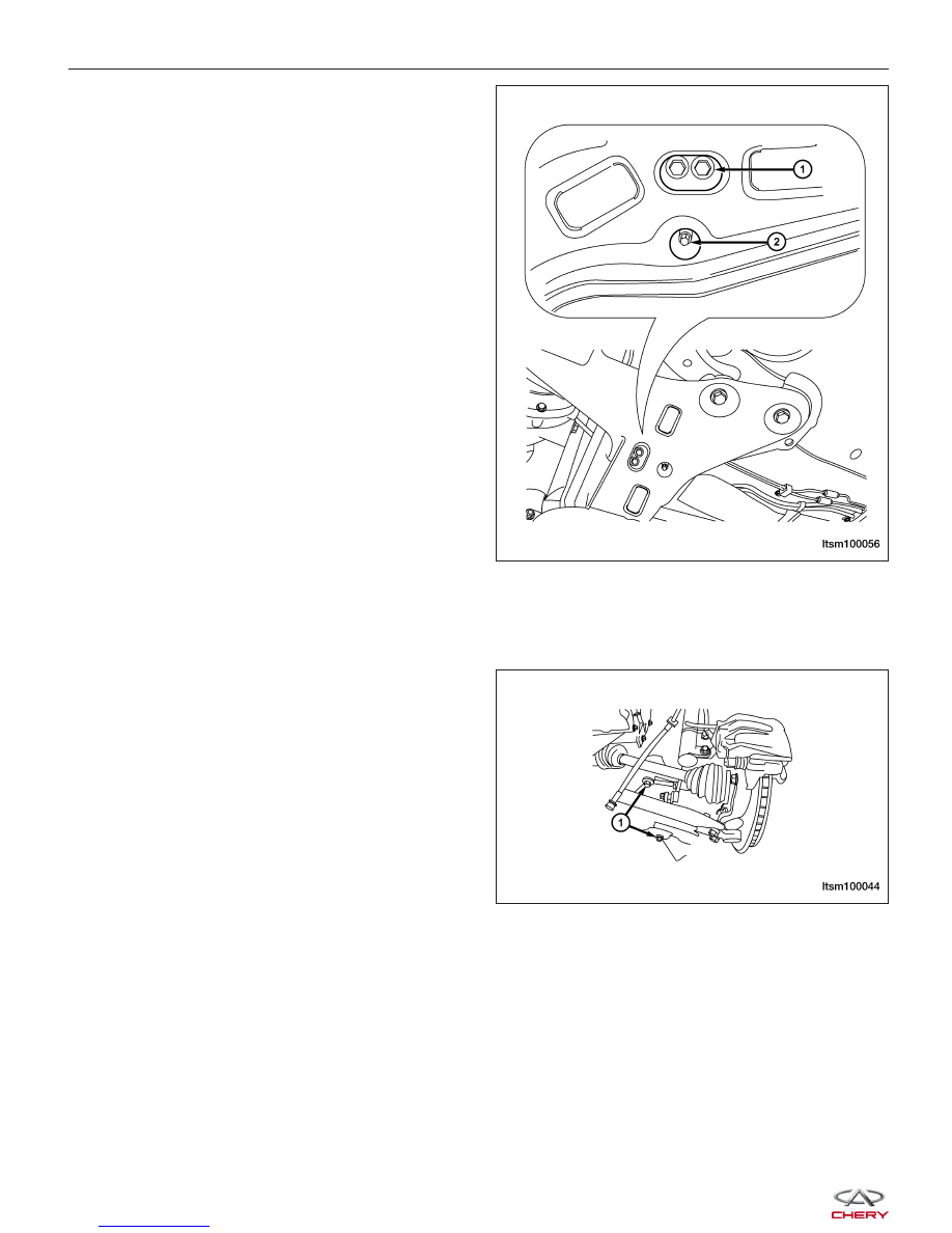
15. Remove the bolts (1) and nut (2) between the sub-

frame assembly and side member assembly.
(Tighten: Sub-frame assembly retaining bolts to
120 ± 5 N·m)

16. Remove the bolts between the radiator lower seat and side member assembly, then remove the side member

assembly.

17. Remove the front engine mount and rear engine mount (See Engine Mounts Removal & Installation in Section

02 Engine).

18. Remove the bolts (1) between the sub-frame

assembly and the vehicle body.
(Tighten: Sub-frame assembly to vehicle body bolts
to 180 ± 15 N·m)

19. Remove the sub-frame assembly.

20. Separate the front lower control arm and the front stabilizer bar from the sub-frame assembly.

21. Installation is in the reverse order of removal.

ON-VEHICLE SERVICE

LTSM100056

LTSM100044


UNIT REPAIR

Front Strut

Disassemble

NOTE :
The strut assembly must be removed from the vehicle for it to be disassembled and assembled. For the disassembly
and assembly of the strut assembly, use a strut spring compressor, or the equivalent, to compress the coil spring.
Follow the manufacturer’s instructions closely.

1. Remove the front strut assembly (See Front Strut Removal & Installation in Section 10 Suspension).

2. If both struts are being serviced at the same time, mark both the coil springs and strut assemblies according to

which side of the vehicle the strut is being removed from.

WARNING!

Do not remove the strut rod nut before the coil spring is properly compressed. The coil spring is held under
pressure. The coil spring must be compressed, removing spring tension from the upper mount and bearing,
before the strut rod nut is removed.

3. If the spring compressor fixture is unable to attach

to a workbench, attach the spring compressor to a
bench vise.

4. Position the strut assembly in the strut coil spring

compressor following the manufacturer’s instruc-
tions and set the lower and upper hooks of the
compressor on the coil spring.

5. Loosen the spring compressor, then attach the

clamps between the top and bottom of the spring.

6. Compress the coil spring until all coil spring tension is removed from the upper mount and bearing.

CAUTION:
Never use impact or high speed tools to remove the strut rod nut. Damage to the strut internal
bearings can occur.

LTSM100013

LTSM100014

10


7. Once the spring is sufficiently compressed, install

the strut nut wrench on the strut rod nut.

8. Install a deep socket on the end of the strut rod.

While holding the strut rod, remove the nut using
the strut nut wrench.
(Tighten: Strut rod nut to 100 - 120 N·m)

9. Remove the lower spring isolator from the strut seat.

10. Remove the dust shield and jounce bumper.

11. Remove the upper mounting bracket.

12. Remove the upper spring seat and isolator.

13. Release the tension from the coil spring by backing off the compressor drive completely. Release the compressor

hooks and remove the coil spring.

Inspection

Inspect the strut assembly for damage and evidence of fluid running from the upper end of the fluid reservoir (actual
leakage will be a stream of fluid running down the side of the reservoir tube and dripping off lower end of unit).

Inspect the strut assembly components for the following and replace as necessary:

• Inspect the strut (damper) for shaft binding over the

full stroke of the shaft.

• Inspect the jounce bumper for cracks and signs of

deterioration.

• Inspect the dust shield for cracks and tears.

• Check the upper mount for cracks and distortion

and its retaining studs for any sign of damage.

• Check the bearing and upper spring seat for any

binding.

• Inspect the upper and lower spring isolators for

material deterioration and distortion.

• Inspect the coil spring for any sign of damage to

the coating.

Strut Disposal Procedure

NOTE :
Follow the procedure below to properly dispose of the strut assembly.
• Pull the strut rod to extend the strut rod out as far as possible.

UNIT REPAIR

LTSM100015

LTSM100011


• Drill a hole to discharge the gas (fluid) in the strut assembly cylinder (Drill a hole in the cylinder body according

to the figure to discharge the gas).

Assembly

1. Replace all necessary parts prior to reassembly:

       1. Cushion Pad
       2. Dust Boot
       3. Cushion Block
       4. Upper Spring Seat
       5. Upper Spring Mount

2. Mount the new strut assembly into the fixture.

3. Insert the coil spring into the spring compressor.

4. Compress the coil spring to a distance of

≤120 mm

between the two clamps.

UNIT REPAIR

LTSM100012

LTSM100016

LTSM100017

LTSM100018

10


Content   ..  329  330  331  332   ..