Chery Tiggo. Manual - part 247


  Index      Chery     Chery Tiggo - service repair manual 2009 year


Search            


Content   ..  245  246  247  248   ..


Chery Tiggo. Manual - part 247


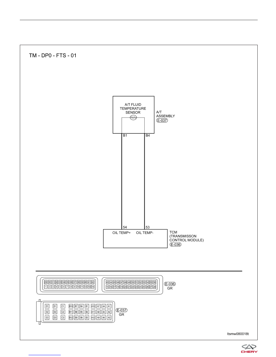
P0710 - Fluid Temperature Sensor

FTS

DIAGNOSIS & TESTING

LTSMW080018T


On Board Diagnostic Logic
• Self-diagnosis detection logic.

DTC NO.

DTC DEFINITION

DTC DETECTION

CONDITION

DTC SET

CONDITION

POSSIBLE CAUSE

P0710

Transaxle Fluid
Temperature (TFT)
sensor

Engine is running

The Transaxle
Control Module
(TCM) will set this
DTC when the
transaxle
temperature does
not reach a normal
operating
temperature within a
given time frame.

• TFT sensor

• Harness or
connectors (The
sensor circuit is open
or shorted)

• Transaxle Control
Module (TCM)

DTC Confirmation Procedure:

Before performing the following procedure, confirm that battery voltage is more than 12 V.

• Connect the X-431 scan tool to the Data Link Connector (DLC) - use the most current software available.

• Turn ignition switch on, with the scan tool, view and erase stored DTCs in the TCM.

• Start the engine and warm it to normal operating temperature.

• With the scan tool, select view DTC and data stream.

• If the DTC is detected, the DTC condition is current. Go to Diagnostic Procedure - Step 1.

• If the DTC is not detected, the DTC condition is intermittent (See Diagnostic Help and Intermittent DTC Trou-

bleshooting in Section 08 Transaxle & Transfer Case for more information).

NOTE :
While performing electrical diagnosis & testing, always refer to the electrical schematics for specific circuit
and component information.

DIAGNOSIS & TESTING

08


Diagnostic Procedure

1.

CHECK A/T FLUID TEMPERATURE SENSOR RESISTANCE

• Turn the ignition switch off.

• Disconnect A/T assembly connector E-037.

• Check TFT sensor resistance between sensor terminals, component side.

TFT SENSOR RESISTANCE

TEMPERATURE

(°C)

RESISTANCE

-50

93917

-30

28237.4

-10

9826

0

6079

20

2528.5

25

2063

40

1159.2

50

810.4

70

419.1

80

309.2

100

176.2

120

105.9

140

66.7

Is the check result normal?

Yes

>>

Go to the next step.

No

>>

Replace the TFT sensor.

DIAGNOSIS & TESTING


2.

CHECK TFT SENSOR POWER SUPPLY

• Turn ignition switch on.

• Check power supply between A/T assembly terminal B1 and ground.

TFT SENSOR VOLTAGE

A/T ASSEMBLY

CONNECTOR

TERMINAL

TERMINAL

VOLTAGE

B1

Ground

5 V

• 5 V should exist.

Is the check result normal?

Yes

>>

Go to the next step.

No

>>

Repair or replace the open circuit or short to power or short to ground in harness or connectors.
If circuit is normal, replace TCM.

3.

CHECK TFT SENSOR GROUND CIRCUIT

• Turn ignition switch off.

• Disconnect TCM connector.

• Check continuity between TFT sensor connector E-037 and TCM connector E-036.

• Check TFT sensor ground circuit for a short to ground and short to power supply.

Is the check result normal?

Yes

>>

Go to the next step.

No

>>

Repair or replace the open circuit or short to ground or short to power supply in harness or connec-

tors.

4.

CHECK DTC

• With the X-431 scan tool, read TCM DTCs.

• Refer to ⬙DTC Confirmation Procedure⬙.

Is DTC P0710 still present?

Yes

>>

Replace the TCM.

No

>>

The system is now operating properly.
Reassemble the vehicle and road test to verify the customers complaint is repaired.

DIAGNOSIS & TESTING

08


Content   ..  245  246  247  248   ..