Chery Tiggo. Manual - part 242


  Index      Chery     Chery Tiggo - service repair manual 2009 year


Search            


Content   ..  240  241  242  243   ..


Chery Tiggo. Manual - part 242


Diagnostic Trouble Code (DTC) Tests
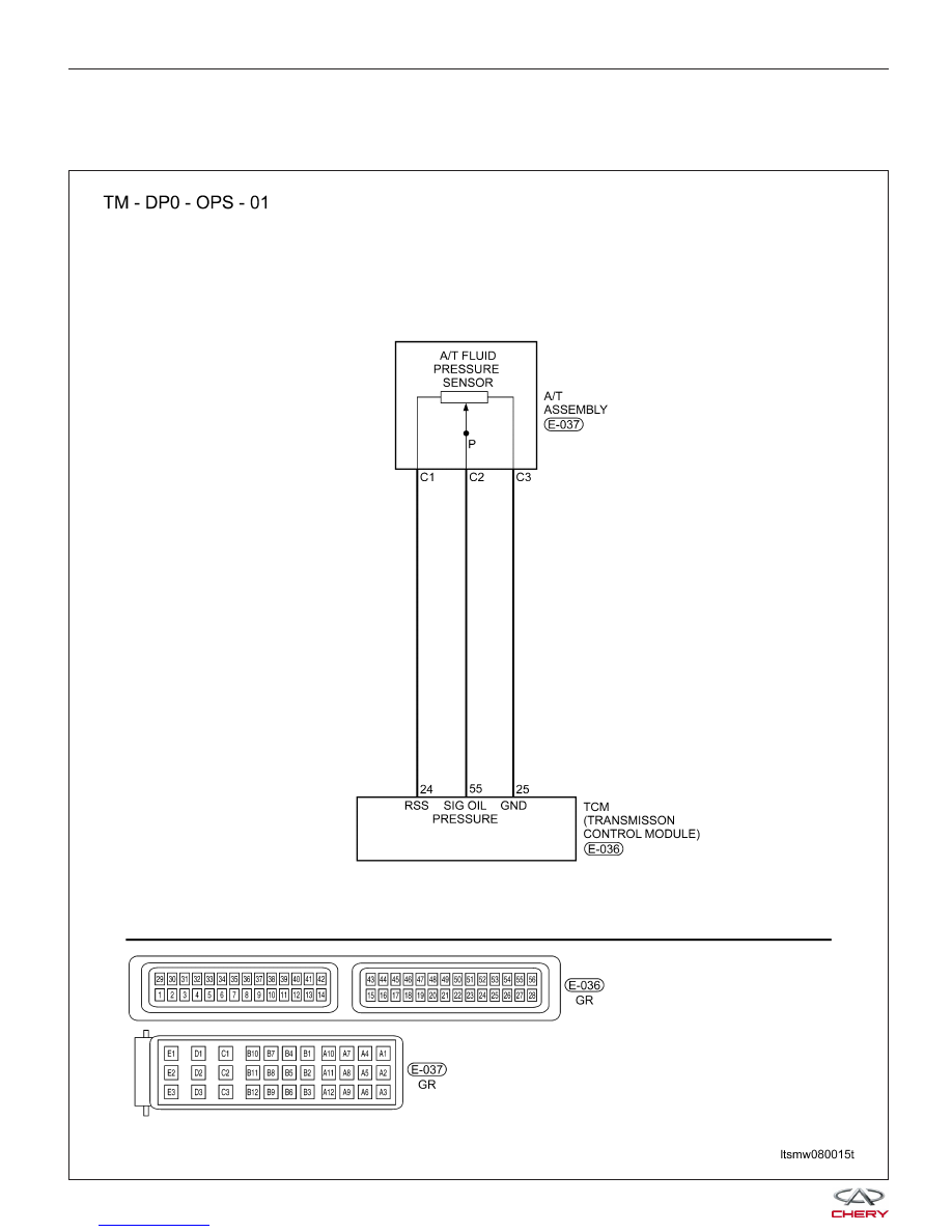
P0641 - Sensor Feed

DIAGNOSIS & TESTING

LTSMW080015T


A/T Fluid Temperature Sensor

DIAGNOSIS & TESTING

LTSMW080018T

08


On Board Diagnostic Logic
• Self-diagnosis detection logic.

DTC NO.

DTC DEFINITION

DTC DETECTION

CONDITION

DTC SET

CONDITION

POSSIBLE CAUSES

P0641

Sensor feed

Engine is running

The Transaxle
Control Module
(TCM) detects that
the voltage is out of
the acceptable
range.

• TFT sensor

• A/T fluid pressure
sensor

• Harness or
connectors (The
sensor circuit is open
or shorted)

• Transaxle Control
Module (TCM)

DTC Confirmation Procedure:

Before performing the following procedure, confirm that battery voltage is more than 12 V.

• Turn ignition switch off.

• Connect the X-431 scan tool to the Data Link Connector (DLC) - use the most current software available.

• Turn ignition switch on, with the scan tool, view and erase stored DTCs in the TCM.

• Start the engine and warm it to normal operating temperature.

• With the scan tool, select view DTC and data stream.

• If the DTC is detected, the DTC condition is current. Go to Diagnostic Procedure - Step 1.

• If the DTC is not detected, the DTC condition is intermittent (See Diagnostic Help and Intermittent DTC Trou-

bleshooting in Section 08 Transaxle & Transfer Case for more information).

NOTE :
• If DTCs P0840 and P0710 are present, diagnose and repair them before continuing with this test.

• Using the appropriate diagnostic test tool, you can diagnose the TCM harness while the TCM is still connected.

This will help prevent electrical connector terminal damage.

NOTE :
While performing electrical diagnosis & testing, always refer to the electrical schematics for specific circuit
and component information.

Diagnostic Procedure

1.

CHECK TRANSAXLE FLUID PRESSURE AND TEMPERATURE SENSOR ELECTRICAL CONNECTOR

• Turn the ignition switch off.

• Disconnect the A/T assembly electrical connector

E-037 (1).

• Inspect the electrical connector for damage.

Is the electrical connector OK?

Yes

>>

Go to the next step.

No

>>

Repair or replace the electrical connector

as necessary.

DIAGNOSIS & TESTING

LTSMD080023


2.

CHECK TRANSAXLE FLUID PRESSURE AND TEMPERATURE (TFT) SENSOR POWER SUPPLY

• Turn the ignition switch on.

• Check the A/T fluid pressure sensor voltage supply

circuit for 5 V between connector E-037, terminal
C1 and ground.

• Check the Transaxle Fluid Temperature (TFT) sen-

sor voltage supply circuit for 5 V between connec-
tor E-037, terminal B1 and ground.

Is 5 V present at each terminal?

Yes

>>

• Go to the next step.

No

>>

• Repair or replace open circuit or short

to ground or short to power in harness
or connectors.

3.

CHECK A/T FLUID PRESSURE SENSOR AND TFT SENSOR GROUND CIRCUIT

• Disconnect the Transaxle Control Module (TCM) electrical connector E-036 (1).
• Check the A/T fluid pressure sensor ground circuit

between the A/T connector E-037, terminal C3 and
TCM connector E-036 terminal 25 for an open,
short to ground or short to voltage.

• Check the A/T TFT sensor ground circuit between

the A/T connector E-037, terminal B4 and TCM
connector E-036 terminal 53 for an open, short to
ground or short to voltage.

Is the check result normal?

Yes

>>

Go to the next step.

No

>>

Repair the circuit for an open or short to

ground or short to voltage in the harness or
connectors.

DIAGNOSIS & TESTING

LTSMD080024

LTSMD080074

08


Content   ..  240  241  242  243   ..