Chery Fora (Elara A520). Manual - part 193
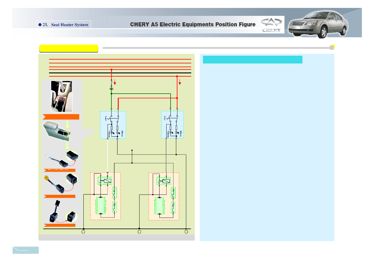
Seat Heater System
(1)Front left seat he ater
(2)Front rig ht seat h eater
◆Control circ uit
◆Main circuit
◆Control circ uit
◆Main circuit
When press the front left seat heating switch, the voltage of ACC2 wire→
15 A Fb6 fu se→2nd p in of front left seat heating switch→contact point of f ront left
seat heating switch→ 4th pin of front left seat h eating switch→1s t pin of f ront left
seat heating set→3rd pin of fr ont left seat heatin g set→gr ound.
The p ositive p ole of ba ttery→FB32 fuse in positiv e pole fu se box→ 2nd pin
of the front left seat heating set→go through the heating wire and relay contact
point in th e front le ft seat he ating set→3rd pin of the front left seat heating set→
ground. Th e front le ft seat he ater heat ing then.
The v oltage of ACC2 w ire→15A Fb6 fuse→2nd pin of front left seat heating
sw itch→contact poi nt of front left seat heating switch→ 3rd pin of front left seat
heating switch→ground. The left heat indicator lamp light on.
When press the front ri ght seat heating sw itch, the voltage of ACC2 wire→
15 A Fb6 fu se→2nd pin of fro nt right seat heat ing switc h→contact point of front
right seat h eating sw itch→ 4th pin of front right seat h eating sw itch→ 1st pin of
fro nt right seat heati ng set→3rd pin of front rig ht seat he ating set→ground .
The p ositive p ole of ba ttery→FB32 fuse in positiv e pole fu se box→ 2nd pin
of the front right seat heating set→go through the heating wire and relay contact
point in th e front r ight seat heating set→3rd pin of the front r ight seat heating
set→ground. The front right seat heater heating then.
The v oltage of ACC2 wire→ 1 5A Fb6 fuse→ 2n d pin of front right seat
heating swi tch→con tact point of front right seat heating switch→ 3rd pin of front
right seat heating sw itch→gro und. The right he at indicator lamp light on.
Seat Heater System Circuit Analysis:
30
15
ACC1
ACC2
31
I LLUM
FB6
15A
1
2
4
3
2
1
4
3
8
31
Gr een Black
Red
R ed
Gre en Black
B lack
Blac k/White
Black/White
Black
Front Left
Seat Heater
Switc h
Fron t Right
Seat Heater
Switch
8
8
To
P ositive Fuse Box
Front Left Seat Heater
Device
F ront Right Seat Heater
De vice
2
1
3
2
1
3
L16
Figure21-1
Circuit Diagram
Seat Heater System
The installati on position of seat
heating switc h
F/L seat heating switc h
F/R seat heating switch
Rear seat heating s witch
4 2