Chery Fora (Elara A520). Manual - part 186


  Index      Chery     Chery Fora (Elara A520) - service repair manual


Search            


Content   ..  184  185  186  187   ..


Chery Fora (Elara A520). Manual - part 186


Engine management system is mainly composed of sensor、electronic control unit(ECU) and actuator three parts. It controls the basic air intake volume、fuel inject volume

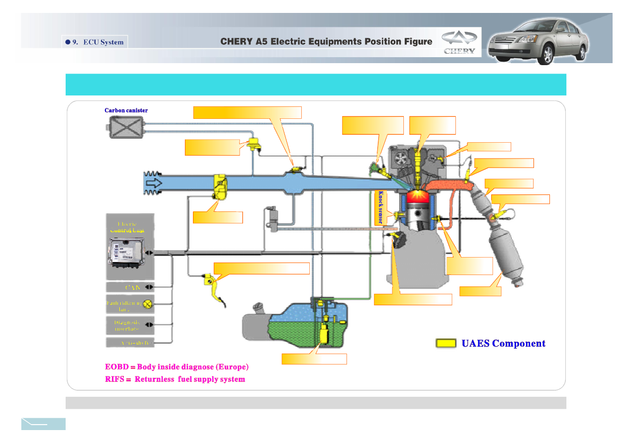
and ignition advance angle when then engine is running. The A5 automobile apply the ME7.9.7 electric control system, the constitution is shown as figure 9-2:

9-2 ME7.9.7 Electric Control System Constitution

Figure

Air intake pressure temp erature sensor

Carbon canister
control Valve

Thr ottle valv e

Accelarate pedal position sensor

Electric fuel pump

Crankshaft position se nsor

Coolant tempe-
rature sensor

Rear o xygen se nsor

Front catalyst

Front oxygen senso r

Spark plug

Fuel distribution
pipe assembly

Phase sensor

Mai n catalyst

1 4

Fau lt descri ption:

Trouble Analysis:

Idle speed no t stable、 can not well accelerate、 can not start、 idle speed is too

high、the exhaust e xceeds the standard、 starts difficult、 A/C invalidation、 fuel in jector
control in validation、 flameout and etc.

( 1) The over loading of outer conne ct set re sults in the burn of ECU inner

components, which leads to invalidation.

(2)Water gets into the ECU and results in the rust in the line board.

Start the ignition switch, use the engine data K wire (the standard diagnosis plug 7# pin )

ground (that's to connect the 4# and 7# pin of diagnosis plug with a lead) over 2.5s, if there is
DTC in the ECU fault memorizer, the engine fault lamp will output the flash code, that's P-

Troubleshoot:
(1) (con nect the plug) u se the e ngine da ta K wire to read engine fault

record

(1)Air Flow Meter

The air flow mete r( MAF) sensor measures the volume of air that inhaled into th e

engine. Engine control module( ECM)uses the da ta to calc ulate the spout time、ignitio n
timin g and engine load.

Sensor invalidation result from the pollution of dust、oil and water.

The 1st pin is air intake temperatur e pressure sensor, connectin g to the 42nd pin of

ECU; the 3rd pin grou nds and connects to the 17th pin of ECU;the 4th pin inputs 5V
refer ence voltage, and connect to 33rd pin of ECU; the 2nd pin input s 14V rati ng voltag e;
the 5 th pin is output vo ltage, and connects to the 37 th pin of ECU.

Check the output voltage of 5th pin, if it is over 1.025V, the n the sen sor will be

disqualification.

If it is p rimarily diagnosed as the s ensor's t rouble, c onnect th e

emission analyzer and c heck the performan ce in the two working cond ition.

Trouble analysis:

Troubleshoot:

Static state test(zero flu x test):

Dynamic test:

ECU receives and deals with the engine state signals which is inputted by each sensor,

and drive each actuator work . It enable s the engine work a ccording to established proc edure
and insures the well motivity、fuel economy and drain performance.

◆ Engine ECU

Figure9-4 Diagnosis plugs

◆Input signal

Figure9 -5 Air f low meter and its circuit diagram

Figure9 -3 Engine ECU

ECU(EMS)Engine

Engin e computer is installed
at the passenger side

The inst allation po sition
of engin e computer

Air flow me ter

1 7

42

37

33

ECU

3

1

5

4

2

To main r elay

Air flow meter

CODE. For example: the flashing of P0203 is : flash 10 times continuously-intermission-flash 2
times continuously-intermission-flash 10 times continuously-intermission-flash 3 times
continuously.

( 2) ( Remove the plug) check whether the ECU connect lines are well, and

whether the ECU power、ground is normal.

( 3) Check whether the working of outer sensor is normal, whether the output

signal is creditable and whether the line is well.

(4)Check whether the working of actuator is normal and whether the line is well.
(5)Finally replace the ECU to test.

15

Remark:There is no air flow meter in t he 1.6L engine elctronic
control system,and what instead is the air temperatur e sensor.

Air intake te mperature sensor

(Only for 1.6 L engine)

(Only for 2. 0L engine)

The crankshaft position sensor is to supply engine speed、 crankshaft rotating angle and

TDC signal to ECU. I t is used to control the engine ignition and fuel eject timing.

Ω ±

fault phenomeno n.

remove the plug, set the multimeter at the OHM position , the two

pens conn ect to the 2nd、3rd pin respectiv ely. The rating resistance will be 860

10 %

when it is 20 .

Fau lt description
Trou bleshoot:

The sensor supply the crankshaft phase information to ECU, that's to distinguish the

compression TDC and exhaust TDC.

The 1st pin is the motor anod e, connect to the 66th and 67th pin of ECU;
The 2n d pin is the potentiometer cathode, conenct to the 78th pin of ECU;
The 3rd pin is the potentiome ter anode, connect to the 32nd pin of ECU, 5V power;
The 4th pin is the motor catho de, connec t to the 64th and 65th pin of ECU;
The 5th pin is the signal output 1, conne ct to the 38 th pin of EC U.
The 6th pin is the signal out put 2, conn ect to the 5 4th pin of ECU.

Description of e lectric throttle pin:

(3)Crankshaft position sensor

(4)Phase sensor (camshaft position sensor)

Figure9-7 Cranks haft posit ion sensor and its ci rcuit diagram

can not start, emission exceed standard, fuel consumption increased

and so on.

Fault description:

Troubleshoot:

( connect the plug) start the ignition switch but not the engine, set the

multimeter at the DC volt position, connecting the two pens to the 3rd、1st pin of sensor, confirm
that there is a reference voltage of 12V. Start the engine, then check whether the 2nd pin signal is
normal by using the oscillograph.

the 1st pin connect to

screen

the 2 nd、 3rd pin

supply signal to ECU, and

connect to the 15th、34th
pin respectively.

15

34

B

P

Crankshaft

Position Sensor

ECU

Crankshaft pos ition sensor

3 2 1

79

ECU

Figure9 -8 Phase sensor and its circu it diagram

Th ere are three pins of phase sensor:
th e 1st pin connect to g round; the
2nd is signal output,connect to the 79th
pin ; the 3rd pin connect to the power
anode.

Phase s ensor

Connect to main relay

Phase s ensor

Connect to ground

Figure9 -6 Electric throttle position sensor and its circuit diagram

54

38

64 67 66 65 78

1 4 2

5 6

3

32

Y/B

ECU/A 1/2

Sb

V

Y

L/W

Gr

Electronic Throttle Valve

ECU

Electric throttle

1#、2# pin is 5V reference voltage anode;
3#、5# pin is 5V reference voltage cathode;
4#、6# pin is signal output voltage signal.

Descripti on of the pins of throttle positio n sensor:

accelarate pedal position sensor

ECU

Accelarate pedal

position sensor

(2)Electric throttle and accelarate pedal position sensor

The driver offer the engine real time torque requirement to ECU with the help of accelerate

pedal, ECU send the impulse signal to the electric throttle according to the information it
gained.Therefore, the motor in the electric throttle run and the throttle open to the required angle.

16

3 2

35

40 16

33 36

The coolant temperature sensor

supply coolant signal to ECU, so as to
enable the start、 idle speed、 ignition
timing and injection impulse width
modify. There are two pins, and they
can exchange to use.

Sta rt

difficultly

( Remove the

plug) Set the multimeter at the ohm
shift, the two pens connect to the 1st、
2nd pin of sensor respectively, the
rating resistance is 2.5kΩ±5% when it
is 20℃. The other temperatures please
refer to table 8-1.

:

Fault descrip tion

Troubleshoot:

can not accelerate well

inds of f luid such as fuel、 coolant、 brake fluid、

water contact to sensor for long time wil result in the erode of sensor.

Remove the plug

Set the multimeter to the ohm position,

connecting the two pens to the 1st、2nd and 1st、3rd pin respectively, and the resistance
in normal temperature should be more than 1MΩ. Set the multimeter at the mV position,
and knock the knock sensor with a hammer gently, then there will be voltage signal output .

Fault description

Troubleshoot

Fault analysis:

:

It

Several k

The oxygen sensor is used to detect th e content of oxygen in th e exhaust,the

transmits a signal to ECU, according to the in formation ECU wi ll make t he fuel closed
loop control so that the engine can work in th e best Condition, and mak e the CO, HC,
NOx comp ound tran sformed and depurated mostly by the three-way catalytic converter .

(5)Knock sensor

There ar e 3 pins on the sensor , the 1st、

2nd pin connec t to the 19th、20th pi n of ECU;

the 3 rd pin con nect to screen.

ECU

19

20

Figure9-9 Knock sensor and its c ircuit diagram

(6)Coolant temperature sensor

ECU

17

39

1 2

Figu re9-10 Coolant temperature sensor and its circuit

(7)Oxygen sensor

Figure9-11 Oxygen sensor and its circuit

The knock sensor supply engine knock information to ECU, and control the knock.

Knock sens or

Knock s ensor

Co olant temperature sensor

Front oxygen sensor

P/Br

2

3

1

4

1

18

Front Oxygen Sensor

Rear Oxygen Sensor

G/B

EC U

Main relay

Rear oxygen sensor

Coolant

tempe rature

sen sor

17

Table 8-1

-10

20

80

8.62…10.28

2.37…2.63

0.299…0.345

(℃)

(kΩ )

Temperature

Resis tance

There are 4 pins on this oxygen senso r

No.1 c onnect to h eating power positive (white)
No.2 c onnects to heating po wer negative (white)
No.3 c onnects to signal neg ative(gra y)
No.4 c onnects to signal pos itive (bla ck)


Content   ..  184  185  186  187   ..