Chery Fora (Elara A520). Manual - part 145
CHERY·A21 SERVICE MANUAL ENGINE EFI SYSTEM
19
3 sensor connectors. The rated resistance is
860Ω±10% When it is 20℃
3.6 PHASE
SENSOR
(CAM
SHAFT
POSITIONING SENSOR)
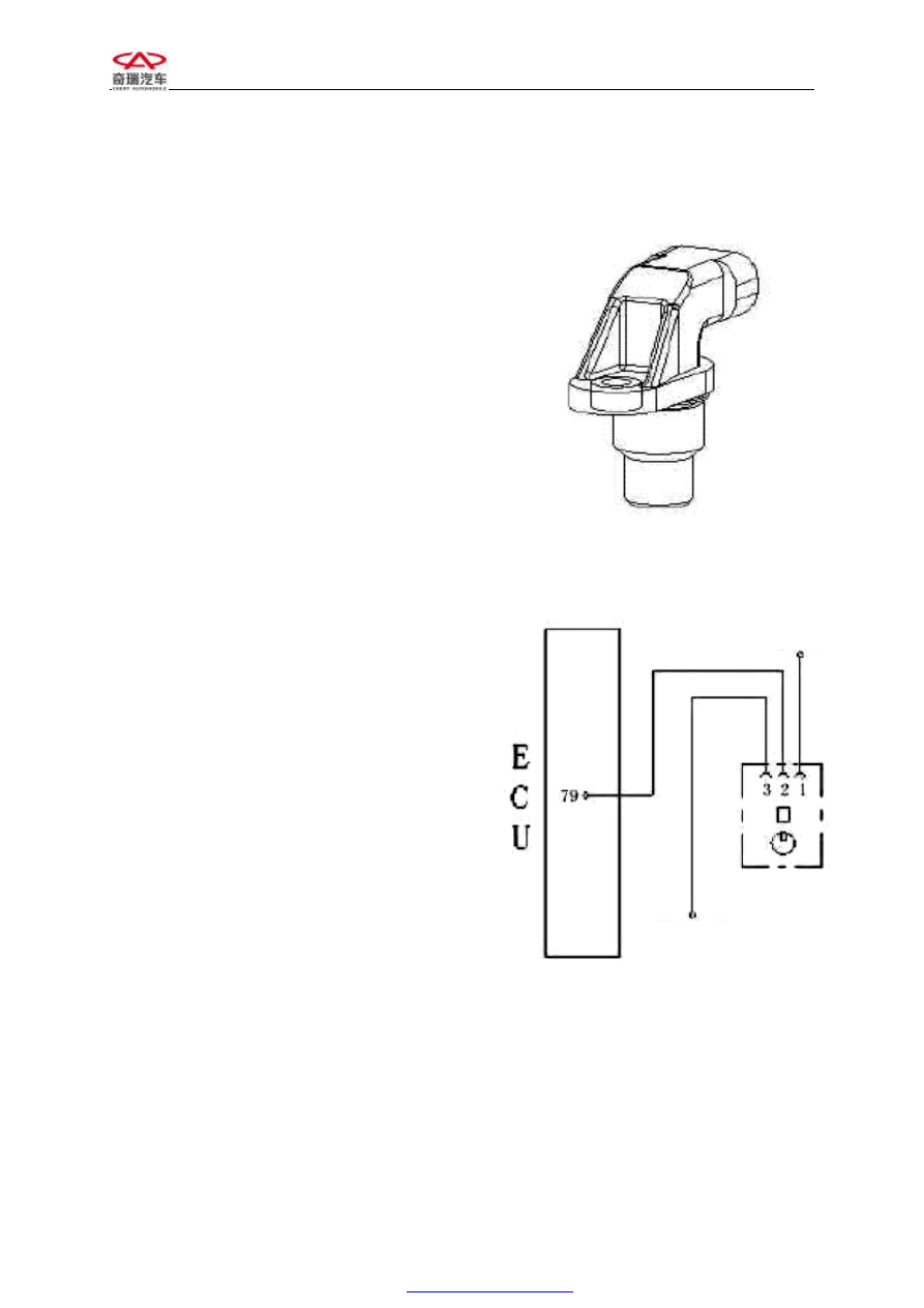
1)Exterior drawing and pin
This sensor has three pins: No. 1 grounding, No.
2 for signal output and No. 3 connecting to
power anode.
2)Installation position: on the valve cover.
There is only one hole on this sensor casing for
tightening M6, and the torque is: 8±0.5Nm.
3)Purpose: This sensor provides crankshaft
phase information to ECU, that is to say, to
separate crankshaft compression top dead center
and exhaust top dead center.
4)Working principle
It is a Hall sensor.
5)Working temperature: -30--130℃
Working voltage: 4.5—16V
Trigger gap: 0.1—1.8mm
6)Malfunction and diagnosis method
l Malfunction: can not start, emission exceed
standard, fuel consume increased.
l Reason: Man made.
l Simple measuring method: (connect the
joint) switch on ignition switch but do not
start the engine; put digital multimeter on
DC volt, connect two meter pen to No. 3
and No. 1 sensor connectors and make sure
there is 12V reference voltage. Start the
engine, checking if it is in good conditions
of No. 2 pin by oscillograph on vehicle.
Chart 3-10 Exterior drawing of phase
sensor
Chart 3-10 Exterior drawing of phase
sensor
Phase sensor
Connect to main relay
Grounding point