Chery A15 / 480 LHD model. Manual - part 76


  Index      Chery     Chery A15 / 480 LHD model - service repair manual


Search            


Content   ..  74  75  76  77   ..


Chery A15 / 480 LHD model. Manual - part 76


COOLING SYSTEM 

DESCRIPTION OF COOLING SYSTEM


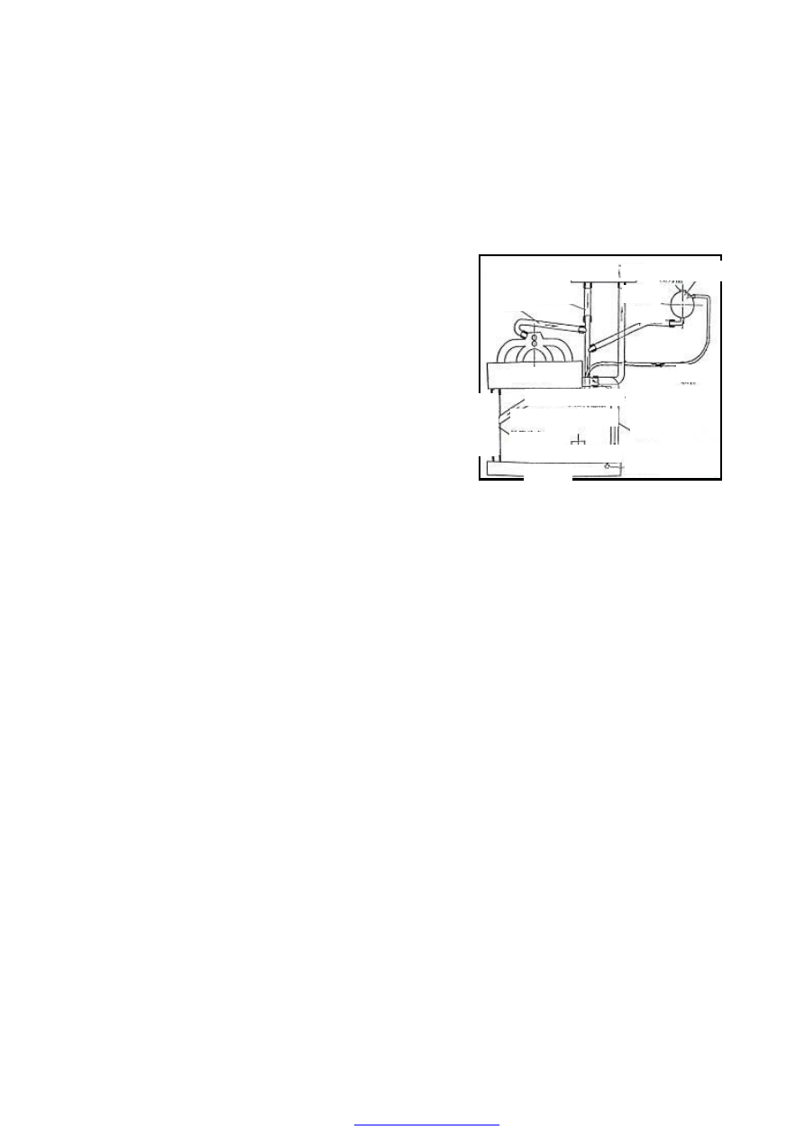
COMPONENTS OF 480 ENGINE COOLING SYSTEM 

Engine  cooling  system  is  used  to  cool  engine  to 

prevent  the  engine  from  overheating,  ensuring  the 
normal  operation  of  engine.  It  is  composed  of  the 
timing  belt-driven  water  pump,  transverse  radiator, 
water tank,  water  pipe,  thermostat, temperature control 
switch  of electrically-driven  fan  and  water temperature 
sensor.   

WORKING PRINCIPLE OF COOLING SYSTEM


When  the  temperature  of  engine  coolant  is 

relatively  low,  the  thermostat  shall  turn  it  off,  and  the 
coolant  shall  circulate  and  flow  among  the  cylinder 
block,  water  pump  and  warm  air  exchanger.  This  kind 
of circulation is called small circulation. 

When  the  temperature  of  engine  coolant  is 

relatively  high,  the  thermostat  shall  turn  it  on,  the 
coolant  shall  flow  into  the  radiator,  the  electrically 
-driven fan shall operate to lower down the temperature 
of coolant. And then the  coolant shall flow  back to the 
engine cylinder block. This kind of circulation is called 
big  circulation.  As  the  big  circulation  operates,  the 
small circulation shall also play its role.       

As  the  engine  works  under  normal  work 

temperature the engine coolant shall expand. Under this 
circumstance,  the  overflow  valve  installed  on  the 
thermostat  chassis  shall  turn  it  on,  the  coolant  shall 
flow  into  the  expansion  water  tank  through  the 
overflow  pipe;  and  as  the  system  cools  down,  the 
coolant  shall  flow  back  to  the  water  pump  inlet  from 
the expansion reservoir.   

The  operation  of  electrically-driven  fan  is 

controlled  by  the  thermo-switch  installed  on  the  right 
water  chamber  of  radiator.  When  the  contact  points  of 
thermo-switch meet together, the electrically-driven fan 
shall run. The water temperature sensor is fitted on the 
back of cylinder head lying at the side of exhaust pipe. 


Hose 

Warm Air/Heat Exchanger 


Expansion Tank 

Pressure Cap 
 

Engine 
 

W

at

er

 P

u

m

p

 Inl

et


Cooling Water Pipe Assembly 

Electrically-Driven Fan 

Thermostat  Chassis  and 
Thermostat Assembly 

Water Temperature Sensor 

Hose 

Hose 

Hose 

Hose 

Radiato

Thermo-Switch 

Hose Assembly 

Hose Assembly 

PARAMETER OF COOLING SYSTEM


Cooling system 

Parameter 

Total system capacity(L)  8 
Engine capacity(L)  3.3 
Radiator capacity(L)  2.1 

Coolant capacity 

Expansion reservoir capacity(L)  0.4 
Diameter: 280mm 
Number of blades: 6 
Operating voltage: 9-15V 
Rotating speed Ι gear: high-speed engine 2000±200         

low-speed engine 1800±200 

Fan   

Rotating speed II gear: high-speed engine    2800±200     

low-speed engine    2600±200 

Diameter of impeller: ф72mm 
Transmission rate: 1.053:1 

Water pump 

Opening pressure of the pressure cap: 160kPa 

Front face area: 0.202m² 

Radiator   

Heat abstraction area:    8.93m² 
Opening temperature: 85º-89º 

Thermostat   

Full opening temperature: 99º-102º 
Switch-on temperature   

gear95 Cº       

gear 102 Cº


Switch-off temperature   

gear≤84 Cº     

gear≤91 Cº


Thermo-switch 

Operating voltage: 12V 


ENGINE COOLANT 

Coolant Discharge: 

――To  demount  the  pressure  cap  of  expansion 

reservoir; 

――To  install  a  vessel  under  the  radiator,  demount 

the  radiator  outlet  hose  under  the  radiator  and 
discharge the coolant.


Cooling System Cleaning: 

――To  discharge  coolant,  mount  the  radiator  outlet 

hose; 

――To  inject  clean  water  up  to  the  position  of  the 

largest  water  surface  of  the  expansion  reservoir 
from the expansion reservoir filler, and then close 
the pressure cap;   

――To start up engine to make it operate at idle speed, 


preheat  up  to  normal  operating  temperature,  shut 
down and cool down;   

――To discharge coolant; 

――To  repeat  the  above-mentioned  steps  until  the 

discharged water is the same as the clean water; 

――To  clean  the  cooling  system  according  to  the 

following  methods  if  the  coolant  is  not  correctly 
used and replaced to meet the requirements in the 
former utilization:   

a.   To discharge coolant; 

b.  To  demount  the  radiator  inlet  hose,  insert  the  main 

water  hose  into  the  radiator  filler  until  the  outlet 
water becomes clean; 

c.   In order to flush out the engine,  you should connect 

the  main  water  hose  with  the  water  outlet  of  the 
thermostat  to  clean  the  engine  until  the  discharged 
water  flowing  from  the  water  pump  inlet  becomes 
clean; 

d. 

  To  repeat  cleaning  operations  if  the  radiator  is  very 

dirty,  and  connect  the  main  water  hose  with  the 
radiator  water  outlet  until  the  water  flowing  from 
the radiator water outlet becomes clean. 


Coolant Filling: 
――To  check  whether  the  pipeline  is  well  connected 

and fastened before injecting coolant; 

――To  open  the  pressure  cap;  fill  up  coolant  into  the 

expansion  reservoir  filler  slowly.  Since  the 
expansion reservoir is at the highest position in the 
cooling  system.  Therefore,  as  the  coolant  level 
rises, the air  in the system  shall  be discharged into 
the expansion reservoir and shall be discharged out 
of  the  expansion  reservoir  by  injecting  coolant 
slowly.   

――To  continuously  inject  coolant  up  to  the  highest 

coolant  level.  And  then  close  the  filler  to  prevent 
coolant from spilling.   

――To  start  up  the  engine  to  make  it  operate  at  idle 

speed  and  preheat  up  to  normal  operating 
temperature.  And  until  the  fan  begins  to  run, 
observe water thermometer and check  if the engine 
is  at  overheating  condition.  If  the  coolant  level  in 


the  expansion  reservoir  descends  quickly,  coolant 
should  be  injected  up  to  the  highest  position  to  cut 
down the air circulation in the system.   

――To shut the engine down to have it fully cooled(if 

possible, leave the engine alone for one night.); 

――To  open  the  pressure  cap  to  check  the  coolant  level,  and 

inject coolant up to the highest position.   

 
Cooling System Checkup: 
――To check the coolant level, start up the engine and 

preheat  it.  Put  the  engine  under  idle  speed 
circumstance  until  the  cooling  fan runs, and  check 
if coolant leakage exists at various pipe joints. Shut 
down the  engine  and  wait  for  engine  cooling. And 
then  check  if  the  coolant  level  in  the  expansion 
reservoir is at normal condition.   

――To  try  best  to  prevent  the  coolant  spilling  from 

scalding operator during checkup.   

To timely check if water flows into the engine oil 

pan  (the  lubricating  oil  shall  become  milk  white 
after  water  flows)  when  no  pipe  leakage  is  found 
and the expansion reservoir is short of coolant, and 
timely stop water from flowing in when finding it. 


COOLING SYSTEM MAINTENANCE WARNING 

Warning

·To try best not to move radiator cap or loose the radiator discharging plug when the engine 

is  under  operation  or  the  engine  and  radiator  are  at a  very  high temperature.  Scorching 
coolant may spill out, hurting the people and damaging the engine and cooling system.   

·To shut down the engine until it cools down, and then carefully demount the radiator cap. 

Meanwhile, wrap a large thick cloth onto the radiator cap, rotate it slowly to the position 
of the first clip along the counter-clockwise direction and then release the pressure slowly.   

·To use a cloth to push down the radiator cap, rotate and remove the radiator cap after the 

operator ensures all the intensity of pressure has been released. 


Content   ..  74  75  76  77   ..