Chery A15 / 480 LHD model. Manual - part 28
The thermo-sensitive resistance is made of a kind of semiconducting material with negative
temperature coefficient, where its resistance will sharply decrease as the temperature
increases.
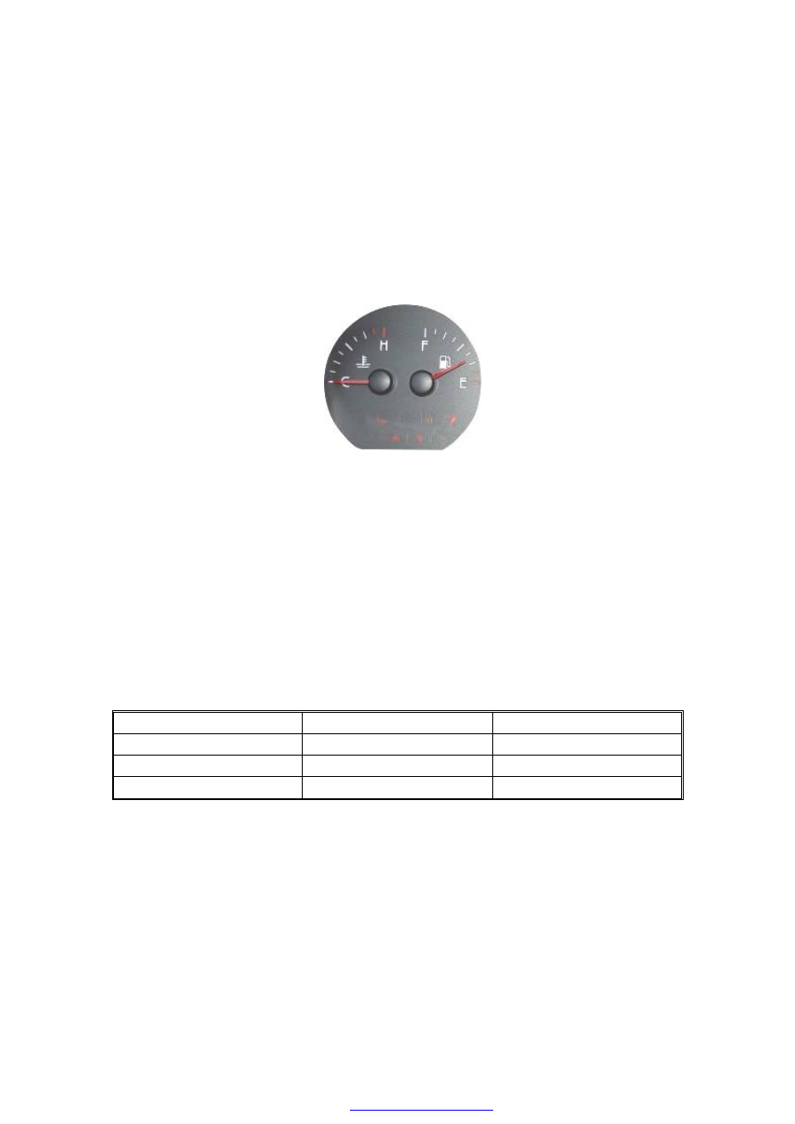
5. FUEL METER
The operation of the fuel meter is basically the same as the water temperature meter. It is also
the cross coil type of indicator needle meter. See figure below (Illustration-5)—the fuel meter
is located at right of the figure.
Fuel meter (Illustration-5)
When the float is moving along with the fuel level in the fuel tank, the sliding contact linked
with the float staff will respond accordingly so as to change the value of the thick-film
resistance. When the fuel tank is full, the value of the thick-film resistance will be the
minimum and the current of the cross coil will be the maximum. The indicator needle of the
fuel meter points at the maximum scale F. On the contrary, when the fuel in the tank is
exhausted, the value of thick-film resistance will be the maximum, and the indicator needle
deflexion value of the fuel meter points being the minimum scale E.
The relationship between fuel quantity and resistance is indicated in the table below.
The relationship between fuel quantity and resistance
Float position
Capacity (L)
Resistance (Ω)
Empty
0
283
Half full
30
89
Full
55
36
FAULT DIAGNOSIS AND TROUBLESHOOTING