Chery A15. Manual - part 221


  Index      Chery     Chery A15 - service repair manual


Search            


Content   ..  219  220  221  222   ..


Chery A15. Manual - part 221


  Chery A15 Maintenance Manual  

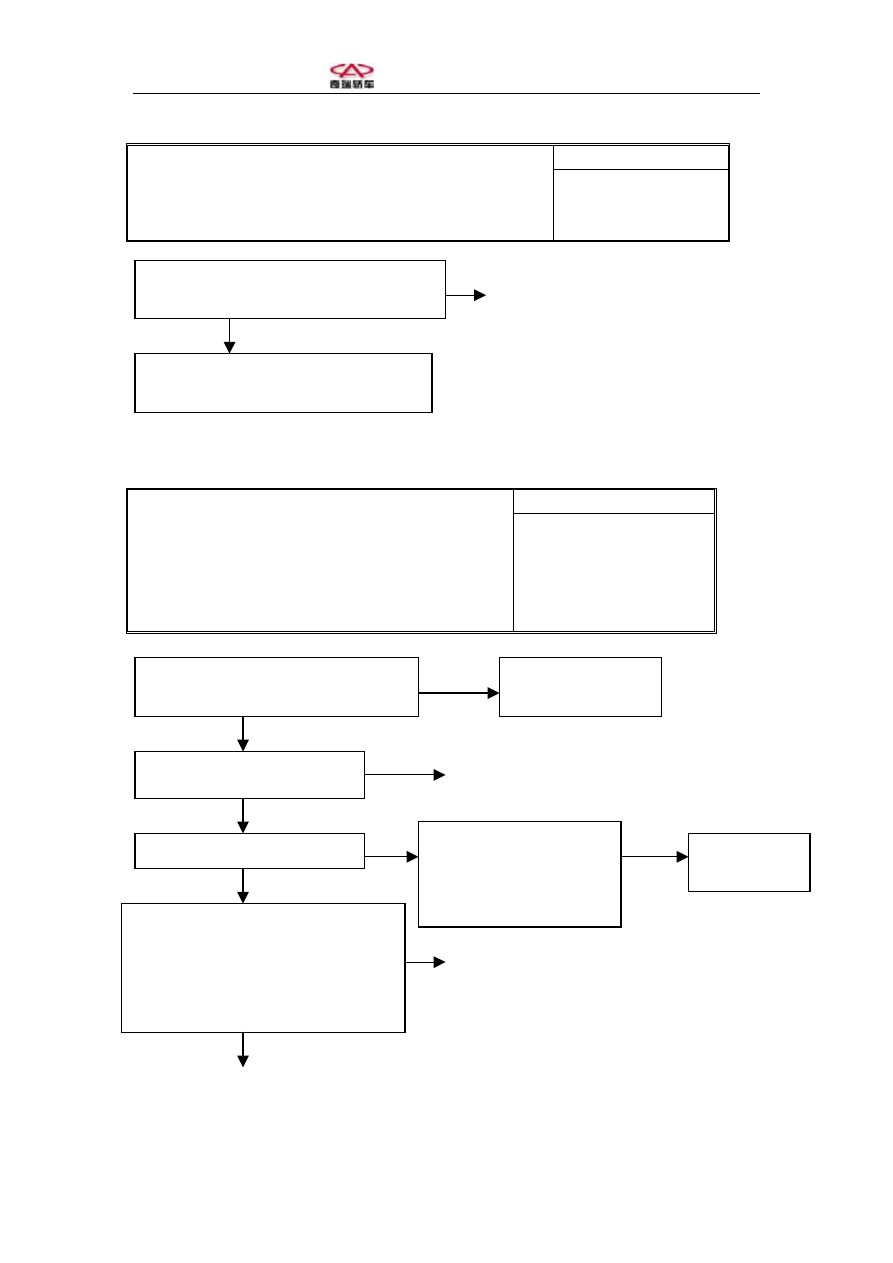
(5). Large force required to operate brake pedal. 

Possible Cause 

[Description]  
Check control booster and brake pedal travel with traditional 
methods, and diagnose normally open valve with fault diagnoser 
hydraulic control unit. 

·

Booster problem 

·

Normally open valve 

problem 


Abnormal 


Replace HCU (hydraulic control unit) 


Normal 


(6). No fault code displayed (communication with fault diagnoser disabled). 

Possible Cause 

[Description]  
This may be caused by open ABS ECU power circuit or 
open diagnose circuit. 

·

Fuse burned 

·

Diagnose wire breakage or 

connector looseness 

·

ABS ECU damage 

·

Fault diagnoser problem 


No


Yes 


Abnormal

Replace 


Normal 


Abnormal 

No


Yes 


                                                              No 

                                                                        Repair diagnose socket or ABS wire harness 


Conduct 


Replace ABS ECU 

Check normally closed valve with hydraulic 

control unit diagnosis of fault diagnoser 

Check booster and pedal travel with 

traditional ABS methods 

Is the diagnoser able to communicate 

with MK20 ABS ECU on other vehicles?

Check ABS power fuse 

Diagnoser fault, 
repair and retest 

Dose diagnoser screen display? 

Demount ABS ECU plug to check if the
related ECU terminal in ABS wire
harness (terminal 7 for MK20I/E) is
conducted to diagnose socket (terminal 7
in diagnoser) 

Repair socket
or wire harness

Check power wire, earthing
wire and diagnose wire in
diagnose socket and their
connections 


  Chery A15 Maintenance Manual  

VIII. ABS System Inspection 

Terminal 

Inspection Item 

Ignition Switch 

Position 

MK20I/E 

Standard Unit 

Battery voltage 
(motor) 

OFF 25-8 

10.1-14.5 

Battery voltage 
(electromagnetic valve) 

↑ 9-24 

↑ V 

Power insulation 

↑ 8-4 

0.00-0.5 

Earth insulation 

↑ 8-24 

↑ V 

Power voltage 

ON 

8-4 

10.0-14.5 

OFF 

Light off 

Visual check 

ON 

ECU 
disconnected 

Light on 

Visual check 

OFF 

Light off 

Visual check 

ABS warning light 

ON 

ECU 
connected 

Light on for 1.7s 
and then off 

Visual check 

Brake light switch 
function pedal 
unpressed 

ON 8-18 

0.0-0.5 V 

Brake light switch 
function pedal pressed 

ON 8-18 

10.0-14.5 

Front left wheel speed 
sensor resistance 

OFF 1-2 1.0-1.3 KΩ 

Front right wheel speed 
sensor resistance 

OFF 19-20 

1.0-1.3 KΩ 

Rear left wheel speed 
sensor resistance 

OFF 5-6 1.0-1.3 KΩ 

Rear right wheel speed 
sensor resistance 

OFF 22-23 

1.0-1.3 KΩ 

Front left wheel speed 
sensor output voltage 

OFF 1-2 3.4-14.8 

mV/HZ 

Front right wheel speed 
sensor output voltage 

OFF 19-20 

3.4-14.8 

mV/HZ 

Rear left wheel speed 
sensor output voltage 

OFF 5-6 >12.2  mV/HZ 

Rear 

right

 wheel speed 

sensor output voltage 

OFF 22-23 

>12.2  mV/HZ 

Sensor output voltage 
ratio 

Highest peak voltage 


        ≦ 2 

Lowest peak voltage 


  Chery A15 Maintenance Manual  

IX. ABS Performance Inspection 

(I). Checking Wheel Speed Sensor Output Voltage


1. Check the clearances between wheel speed sensors and gear rings, which shall 

comply with standard values. 

2. Jack up wheel and release hand brake. 

3. Disconnect ABS wire harness and measure at harness adapter. 

4. Rotate the wheel at the rate of 0.5 turn per second, and measure the output voltage 

with a multimeter or an oscillograph. 

                      MK20 I/E 

                          Terminal 1 - 2 

                          Terminal 19 – 20 

                          Terminal 5 - 6 

                          Terminal 22 – 23 

5. Possible causes of output voltage exceeding above limits: 

. Oversize air gap between sensor and gear ring 

. Sensor fault 

. Check sensor resistance, which shall be 1.0 - 1.3kΩ 

. Check gear ring deformation and air gap between gear ring and wheel speed 

sensor by taking four points on gear ring. 


X. Disassembly and Assembly 

(1). Spare Part Options 

* HECU assembly, dry; 

* Separate HCU and ECU, HCU wet. 

(2). Precautions 

* Identify fault cause with diagnoser before repair; 

* Unpack spare parts only before installation; 

* Use spare parts made by the same manufacturer; 

* Wipe clean with only non-wool cloth; 

  Chery A15 Maintenance Manual  

* Clean part surface with detergent free of mineral oil before manitenance; 

* Do not use compressed air or move the vehicle when opening the system; 

* Block all hydraulic outlets with proper plugs after ABS assembly is demounted; 

* Remove other parts that may interfere with operation; 

* Use DOT 4 brake fluid. Mineral oil is prohibited. 

* Soak sealing part and O-ring in brake fluid. Mobile oil or brake grease are 

prohibited. 

* Check conventional brake system and ABS   

performances after maintenance; 

* Check all hydraulic pipe connections for leakage. 

(3). Disassembling MK20-I HECU 

. Turn off ignition switch and disconnect battery negative   

terminal; 

. Remove wire harness form ABS assembly; 


. Depress the pedal >60mm and secure it with a pedal   

3

2

1

B

bracket to shut off master pump center valve to prevent   

brake fluid from flowing out from outlets when opening   

system; 

. First remove brake rigid tubes A and B connecting HCU   

to master pump and mark the position, then plug up the   

outlet immediately; 

. Remove brake fluid tubes 1-4 connecting HCU to four   

A Front piston    B Rear piston
1 Front right      2 Rear left   
3 Rear right    4 Front left 

wheels and mark the position, then plug up the outlet   

immediately; 

. Remove the nut fixing HECU on bracket; 

. Take the whole HECU off the bracket. 


Content   ..  219  220  221  222   ..