Chery A15. Manual - part 7
TOP AND BOTTOM TIMING GEAR
COVER ASSEMBLY
Removal
Loosen and unscrew two bolts of the top timing
gear cover assembly.
Remove the top timing gear cover and
gasket
assembly.
Remove the gasket from the top timing gear
cover.
Remove the crank pulley.
Loosen and unscrew the two bolts on the timing
gear cover.
Remove the timing gear cover and gasket
assembly.
Remove the gasket from the bottom timing gear
cover.
Installation
Clean the bottom timing gear cover and fix the
new gasket on the bottom timing gear cover with
glue. Install the bottom timing gear cover and
gasket assembly on the crank shaft, screw in two
bolts by hands and tighten them for a moment of
9.0~11N.m.
Clean the top timing gear cover and fix the new
gasket on the top timing gear cover with glue. Fix
the top timing gear cover and gasket assembly on
the cylinder head with two bolts for a tightening
moment of 9~11N.m.
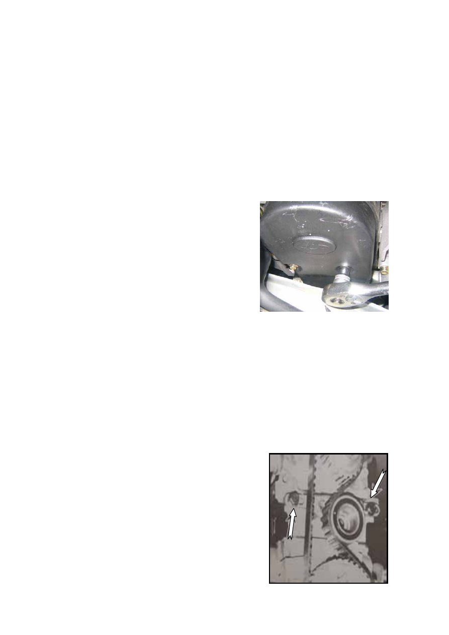
TIMING BELT REMOVAL
Rotate the crank shaft to the compression TDC
on the first cylinder. Loosen the two bolts on the
tension pulley (as indicated by the arrows in the
figure) and push the tension pulley towards one
side by a large-size screwdriver to release the
belt tension.
ENGINE TIMING
B-4