Loader Bobcat 853, 853H. Manual - part 50


  Index      Bobcat     Bobcat 853, 853H loader - service manual


Search            


Content   ..  48  49  50  51   ..


Loader Bobcat 853, 853H. Manual - part 50


ALTERNATOR

Removal And Installation

Engine is operated with battery cables
disconnected.

Battery cables are connected when using a
fast charger or when welding on the loader
(Remove both cables from the battery).

Extra battery cables (booster cables) are
connected wrong.

Damage to the alternator can occur if:

I–2023–1285

NOTE: The engine/hydrostatic pump assembly is

shown removed for photo clarity purpose
only.

Raise the operator cab. (See Page 1–1.)

Open the rear door. Disconnect the negative (–) battery
cable.

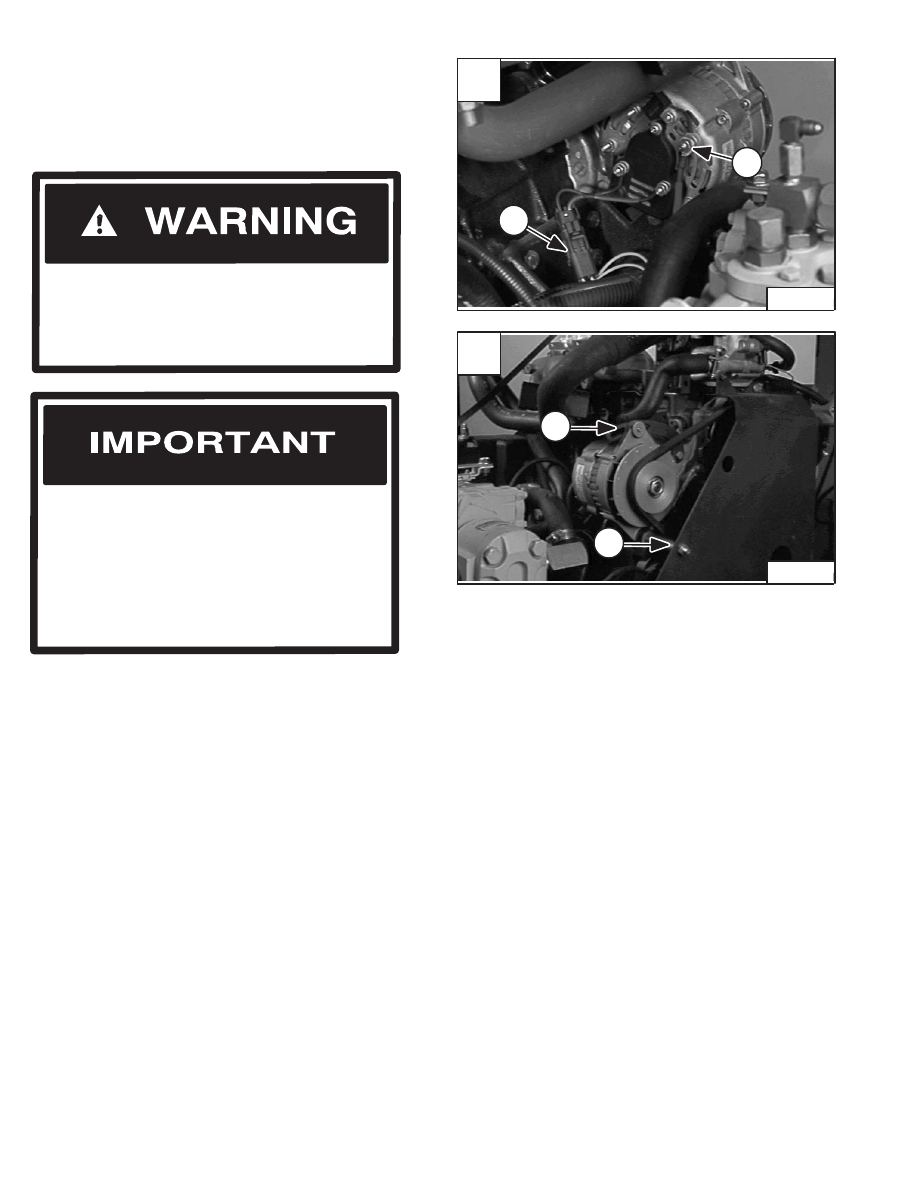
Disconnect the orange wire (Item 1) [A] from the
alternator.

Disconnect the wiring harness connector (Item 2) [A].

Loosen the adjustment bolt (Item 1) [B].

Remove the alternator belt.

Remove the adjustment bolt (Item 1) [B]

Remove the mounting bolt, nut and spacer (Item 2) [B].

Remove the alternator.

Never work on a machine with the lift arms up
unless the lift arms are secured by an approved
lift arm support device. Failure to use an
approved lift arm support device can allow the
lift arms or attachment to fall and cause injury
or death.

W–2059–0598

A

P–04944

2

1

–6–12–

853, 853H Loader

Service Manual

B

P–04945

2

1

ALTERNATOR (Cont’d)

Disassembly 

(Motorola or Prestolite 30 Amp., Enclosed)

Disassemble the alternator as shown in Fig. [A].

Remove the regulator cover and regulator.

Remove the four bolts holding halves together.

Pry the halves apart.

Use a soft jaw vise to hold rotor while removing pulley nut.

Remove front case half from the rotor using a plastic
hammer.

Unsolder the stator leads from the rectifier. Remove the
stator.

Stator Continuity Test

Use an ohmmeter to test the stator.

Touch the probes to two of the bare stator wires [B].

Move one of the probes to the third wire.

The readings should be the same.

If there is no continuity, replace the stator.

Stator Ground Test

Touch one probe to a bare stator lead and the other probe
to the bare metal surface of the stator [C].

There should be no continuity.

Replace the stator if there is continuity.

A

D–01760

  1.  Nut
  2.  Pulley
  3.  Fan
  4.  Bolt
  5.  Case Half (Front)
  6.  Bearing
  7.  Rotor
  8.  Slip Ring
  9.  Stator
10.  Heat Sink (+)

2

16

11.  Heat Sing (–)
12.  Case Half (Rear)
13.  Condenser Assy.
14.  Brush Holder
15.  Regulator

1

3

4

5

6

7

6

9

8

1011

12

13

14

15

B

P–01369

C

P–01386

853, 853H Loader

–6–13–

Service Manual

ALTERNATOR (Cont’d)

Rotor Continuity Test

Touch the probes to the slip rings [A].

The ohmmeter should read between 3.0–33.0 ohms.

If there is no continuity replace the rotor.

Rotor Ground Test

Touch one probe to one of the slip rings and the other
probe to the rotor shaft [B].

There should be no continuity.

Replace the rotor if there is continuity.

Rectifier Continuity (Diode) Test

NOTE: In the diode tests there should be continuity

in one direction only. If the diode being
tested shows no continuity or continuity in
both directions, replace the rectifier
assembly.

Touch the probes to the terminals of each diode and read
the meter [C].

Reverse the probes to check the diode in the other
direction.

There should be continuity in one direction only.

Touch one probe to the diode and the other probe to the
connected  heat sink and read the meter [D].

Reverse the probes to check the diode in the other
direction.

There should be continuity in one direction only.

A

P–01365

C

P–01373

D

P–01370

–6–14–

853, 853H Loader

Service Manual

B

P–01378

ALTERNATOR (Cont’d)

Assembly

Reverse the order of disassembly.

Place the rotor in soft jaws when tightening the shaft nut.
Tighten to 50 ft.–lbs. (68 Nm) torque [A].

Install the rear case half and the remaining parts.

A

P–01808

853, 853H Loader

–6–15–

Service Manual


Content   ..  48  49  50  51   ..