Loader Bobcat 773. Manual - part 121


  Index      Bobcat     Bobcat 773 - service manual 1997 year


Search            


Content   ..  119  120  121  122   ..


Loader Bobcat 773. Manual - part 121


BICS

 VALVE (Cont’d)

Removal And Installation

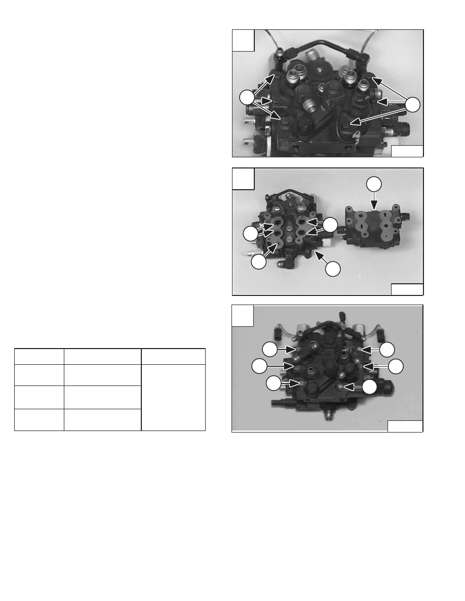
Loosen the six mounting bolts (Item 1) [A] at the BICS
valve.

Remove the mounting bolts (Item 1) [A].

Remove the BICS valve assembly (Item 1) [B] from the
top of the control valve (Item 2) [B].

Installation: Always replace the four large O–rings (Item
3) [B] and small O–ring (Item 4) [B].

Installation: The chart below lists the correct torque
specifications and tightening sequence [C] when
reinstalling the BICS

 valve assembly to the hydraulic

control valve. Thoroughly clean and dry bolts and threads
in valve. Use liquid adhesive LOCTITE #242.

Step

1

2

3*

Torque

110–130 in.–lbs.

(12,4–14,7 Nm)

190–210 in.–lbs.

(21,5–23,7 Nm)

190–210 in.–lbs.

(21,5–23,7 Nm)

Sequence

1, 2, 3, 4, 5 & 6

*Torque must be 190–210 in.–lbs. (21,5–23,7 Nm) for
every bolt or the complete 

sequence must be repeated.

A

N–17271

1

1

C

P–09587

3

1

5

6

2

4

–10–48–

Service Manual

773 BICS Loader

Revised June 01

B

N–17302

1

2

3

3

4

HYDRAULIC CONTROL VALVE

Removal And Installation

Stop the engine. Use the lift lock valve knob to release the
hydraulic pressure. Raise the seat bar.

Lift and block the loader. (See Page 1–1.)

Raise the operator cab. (See Page 1–1.)

Remove the actuators. (See Page 10–29.)

Clean the area around the control valve.

Mark all tubelines for correct installation.

Disconnect the wire harness connectors (Item 1) [A] from
the auxiliary solenoid connectors.

Disconnect the harness connector (Item 2) [A] from the
BICS valve solenoid connector.

Installation: Instll a never modify sta–strap around the
connector (Item 2) [A].

Disconnect the drain hoses (Item 3) [A] from the main
control valve.

Disconnect the outlet tubeline (Item 1) [B] from the
control valve.

Disconnect both tubelines (Item 2) [B] from the auxiliary
section of the control valve.

Disconnect the hose (Item 1) [C] from the lift arm by–pass
control vavle.

Disconnect the tilt tubelines (Item 2) [C].

Disconnect the lift tubelines (Item 3) [C].

Never work on a machine with the lift arms up
unless the lift arms are secured by an approved
lift arm support device. Failure to use an
approved lift arm support device can allow the
lift arms or attachment to fall and cause injury
or death.

W–2059–0598

Raise the lift arms and install an approved lift arm support
device. (See Page 1–1.)

A

N–17819

2

3

4

1

C

N–17821

2

1

3

2

When repairing hydrostatic and hydraulic
systems, clean the work area before
disassembly and keep all parts clean. Always
use caps and plugs on hoses, tubelines and
ports to keep dirt out. Dirt can quickly damage
the system.

I–2003–0888

Service Manual

–10–49–

773 BICS Loader

Revised Nov. 01

B

N–17820

1

2

HYDRAULIC CONTROL VALVE (Cont’d)

Removal And Installation (Cont’d)

Remove the right rear tire.

Locate the rectangular access cover (Item 1) [A] on the
right side of the loader frame.

Loosen one mounting bolt (Item 2) [A] of the access
cover. Remove the control valve mounting bolt (Item 3)

[A]

 from the access cover.

Rotate the cover to expose the access slot in the loader
[B].

Disconnect the inlet hose from the control valve through
the access slot [C].

Remove the control valve mounting bolt (Item 4) [A].

Installation: Tighten the mounting bolt & nut to 18–20
ft.–lbs. (24–27 Nm) torque.

Remove the control valve from the loader.

Reverse the removal procedure to install the control
valve.

A

P–04109

1

2

3

4

C

P–04110

–10–50–

Service Manual

773 BICS Loader

Revised June 01

B

P–04108

A1

Lift Cylinder Base End/Restrictor

A2

Tilt Cylinder Base End

A3

Auxiliary Hydraulics

B1

Lift Cylinder Rod End

B2

Tilt Cylinder Rod End

B3

Auxiliary Hydraulics

C1

Load Check Valve/Lift Function

C2

Load Check Valve/Tilt Function

C3

Orificed Load Check Valve/Auxiliary Function

C4

Outlet Fluid Flow

D1

Lift Spool Centering Spring

D2

Tilt Spool Centering Spring

D3

Auxiliary Spool/Centering Springs

E1

Port Relief Valve – 3500 PSI

E2

Anti–Cavitation/Port Relief Valve – 2500 PSI

F1

Anti–Cavitation Valve

F2

Port Relief Valve

G1

Lift Spool End

G2

Tilt Spool End

G3

Auxiliary Spool/Centering Springs

H1

Auxiliary Electric Solenoid

H2

Plug/Port Relief (Optional) – 2500 PSI

H3

Auxiliary Electric Solenoid

MR

Main Relief Valve – 3000 PSI

HYDRAULIC CONTROL VALVE (Cont’d)

Identification Chart

Item

773 AHC Loader

A

MC–02419

MR

G1

G2

G3

H1

D2

D3

D1

H2

F1

F2

C1

E1

E2

C2

C4

A1

A2

A3

B1

B2

B3

H3

C3

Service Manual

–10–51–

773 BICS Loader

Added June 01


Content   ..  119  120  121  122   ..