BMW 3 (E46). Manual - part 34


  Index      BMW     BMW 3 (E46) - service repair manual 2006 year


Search            


Content   ..  32  33  34  35   ..


BMW 3 (E46). Manual - part 34


Remove housing for interior ventilation
microfilter.

Remove upper cover and
microfilter.

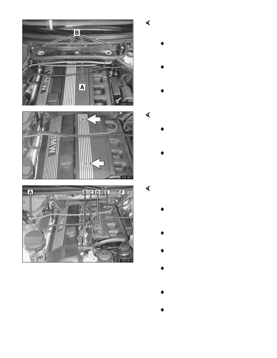
Open wiring harness loom cover
(A) and remove wires.

Unfasten screws (B) and remove
lower microfilter housing.

Remove intake manifold cover:

Remove plastic trim covers
(arrows).

Remove cover hold down bolts
and lift off cover.

Working above engine, detach the
following:

A Positive engine lead at B+
terminal

B Manifold vacuum line

C Oxygen sensor connectors

D Electrical harness connector for
intake air temperature sensor

E Positive lead hold-down bracket

F Resonance valve electrical
connector

CAUTION!

If oxygen sensor harness connectors
are separated, be sure to mark them
so that they can be reassembled as
before.

Working at left rear of engine
compartment:

Peel rubber edge seal off top of
panel.

Twist plastic panel retainers
(arrows) 90° and pull out to
remove.

Disengage panel from hoses and
wiring harnesses and remove from
engine compartment.

Separate brake booster vacuum
hose at one way valve (A). Plug
hose ends.

Detach engine vent hose from cylinder
head cover by squeezing sides of
spring clip (arrows). Detach VANOS
solenoid electrical harness connector
(A).

Detach fuel injector electrical
connectors from injectors:

Use small screwdriver to pry one
corner of wire lock clip on fuel
injector 1 connector.

Repeat for all injectors.

Lift off connector loom and lay
aside.

Remove complete air filter housing:

Detach vacuum line at intake boot
(A).

Disconnect electrical harness
connector on mass air flow sensor
(B).

Release mass air flow sensor clips
(C).

Remove filter housing mounting
screws (D).

Detach air duct connection (E)
and lift complete air filter housing
out of engine compartment,
pulling it forward away from mass
air flow sensor.

Note:

In this step, mass air flow sensor
remains attached to rubber air duct.

Loosen clamps 2 and 8 and remove
mass air flow sensor and air ducts.

1 - Throttle assembly

2 - Hose clamp 77 - 84 mm

3 - Y-duct

4 - Air duct

5 - Hose clamp 83 - 90 mm

6 - Mass air flow sensor

7 - Idle control valve

8 - Hose clamp 28 - 33 mm

9 - Hose clamp 77 - 84 mm

Where applicable: Pull throttle cable
upwards out of rubber retainer (A) and
unhook ball end of cable (B) from
throttle actuator.

Note:

Models equipped with M54 engines do
not use a throttle cable mounted to
throttle housing.

Remove nuts and bolt (arrows)
retaining wiring harness conduit to
throttle body.

Working at throttle housing: Turn
harness plug (arrow) counterclockwise
and remove.

Disconnect electrical harness
connector at idle speed control valve
(arrow).


Content   ..  32  33  34  35   ..