содержание .. 217 218 219 220 ..
Audi TT (2007 year). Manual - part 219
9
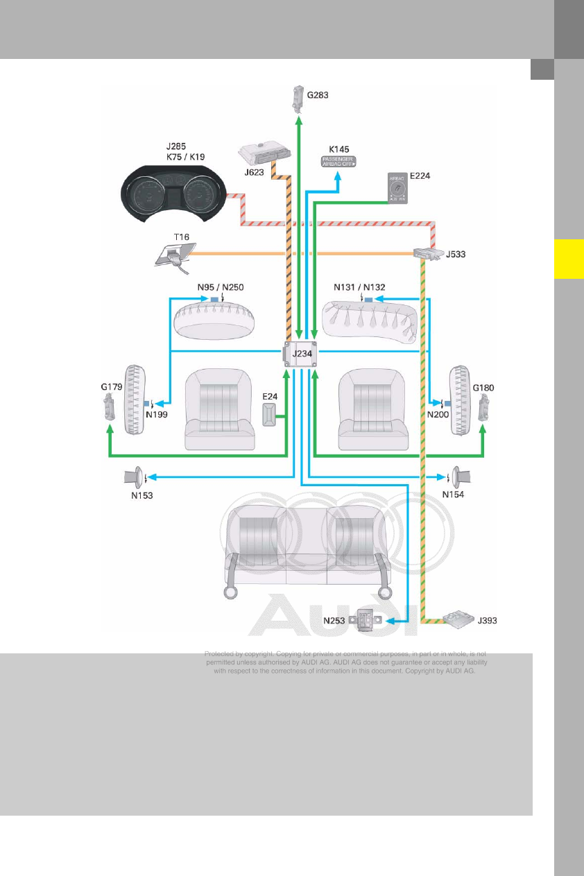
380_005
J234 Airbag control unit
J285 Control unit with display in dash panel insert
J393 Convenience system central control unit
J533 Data bus diagnostic interface (Gateway)
J623 Engine control unit
K19
Seat belt warning system warning lamp
K75
Airbag warning lamp
K145 Front passenger side airbag deactivated
warning lamp (PASSENGER AIRBAG OFF)
N95
Airbag igniter, driver side
N250 Driver side airbag igniter -2-
N131 Front passenger side airbag igniter 1
N132 Front passenger side airbag igniter 2
N153 Driver seat belt tensioner igniter -1-
N154 Front passenger seat belt tensioner igniter -1-
N199 Side airbag igniter, driver side
N200 Side airbag igniter, front passenger side
N253 Battery isolation igniter
T16
16-pin connector, diagnosis connection