содержание .. 56 57 58 59 ..
Audi TT (2007 year). Manual - part 58
Protected by copyright. Copying for private or commercial purposes, in part or in whole, is not
permitted unless authorised by AUDI AG. AUDI AG does not guarantee or accept any liability
with respect to the correctness of information in this document. Copyright by AUDI AG.
2.2
Removing and installing exhaust gas
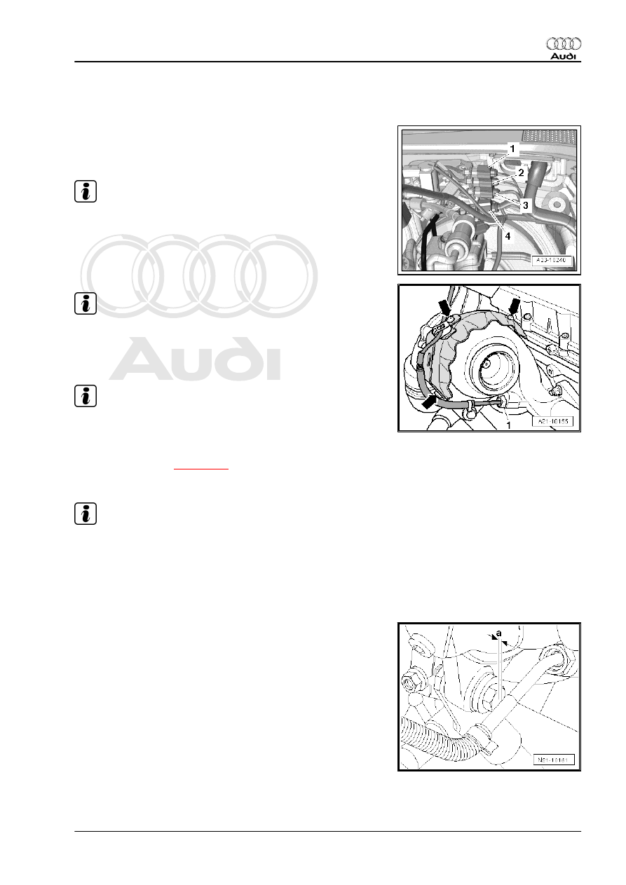
temperature sender 1 -G235-
Removing
– Unplug electrical connector -1- (black) for exhaust gas tem‐
perature sender 1 -G235- and move wiring clear.
Note
Disregard -items 2, 3 and 4-.
Note
The connection can be accessed from below.
– Unscrew exhaust gas temperature sender 1 -G235- -item 1-
from exhaust manifold.
Note
Disregard -arrows-.
Installing
• Tightening torque
Installation is carried out in the reverse order; note the following:
Note
♦
Coat threads of exhaust gas temperature sender with high-
temperature paste; for high-temperature paste refer to ⇒
Electronic parts catalogue .
♦
Fit all cable ties in the original positions when installing.
Installation position of exhaust gas temperature sender -G235- :
• The angled part of the pipe must have a clearance of -a- = 3
… 5 mm from the bolt on the turbocharger support.
2. Exhaust gas temperature control
223