содержание .. 44 45 46 47 ..
Audi TT (2007 year). Manual - part 46
Protected by copyright. Copying for private or commercial purposes, in part or in whole, is not
permitted unless authorised by AUDI AG. AUDI AG does not guarantee or accept any liability
with respect to the correctness of information in this document. Copyright by AUDI AG.
3
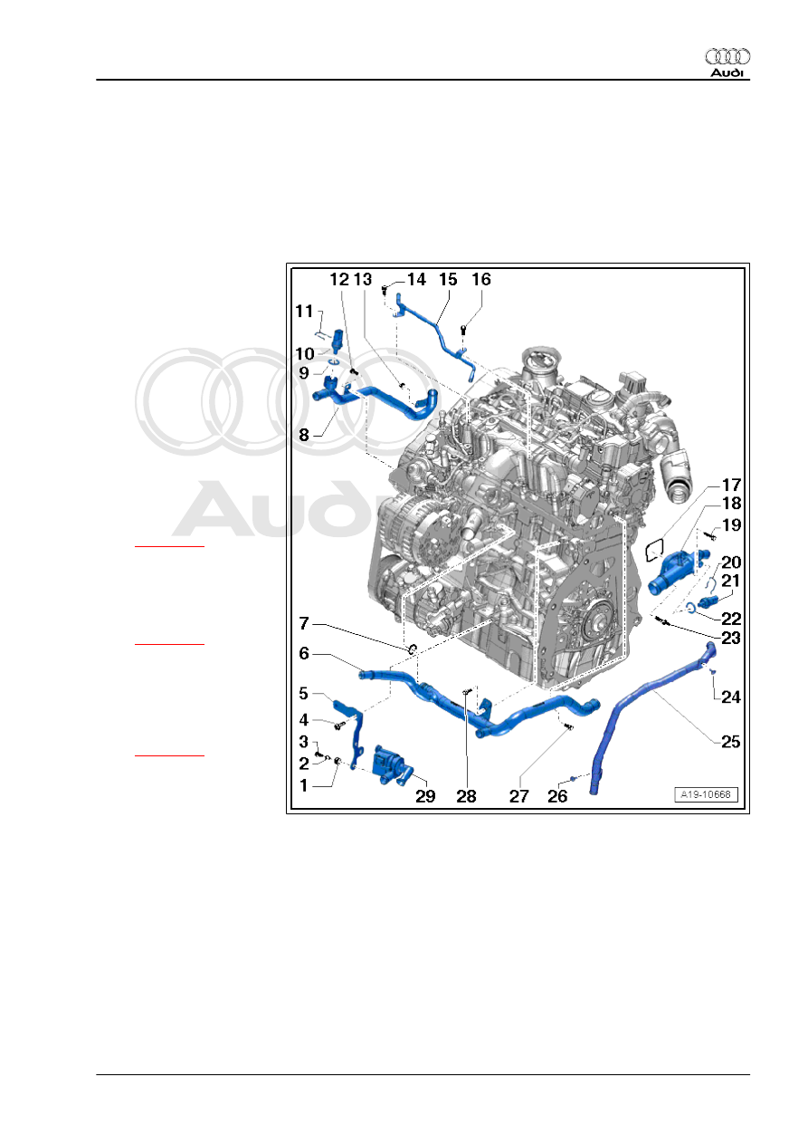
Coolant pipes, coolant temperature
senders, coolant circulation pump
3.1
Coolant pipes, coolant temperature senders, coolant circulation pump - ex‐
ploded view
1 - Grommet
❑ Not supplied separately
2 - Sleeve
❑ Not supplied separately
3 - Bolt
❑ 2.7 Nm
4 - Bolt
❑ 40 Nm
5 - Bracket
❑ For pump for exhaust
gas recirculation cooler
-V400-
6 - Coolant pipe (front)
❑ Removing and installing
7 - O-ring
❑ Renew
8 - Coolant pipe (right-side)
❑ Removing and installing
9 - O-ring
❑ Renew
10 - Radiator outlet coolant
temperature sender -G83-
❑ Removing and installing
11 - Retaining clip
12 - Bolt
❑ 9 Nm
13 - Nut
❑ 9 Nm
14 - Bolt
❑ 9 Nm
15 - Coolant pipe
16 - Bolt
❑ 9 Nm
17 - Gasket
❑ Renew
18 - Connection
3. Coolant pipes, coolant temperature senders, coolant circulation pump
175