Acura RSX Honda Integra. Manual - part 134
+
01
S6M6AALK72100092238FAAT00
+
−
−
−
−
−
−
−
−
−
−
DTC P2238:
YES
NO
YES
NO
YES
NO
YES
NO
YES
NO
11-242
PGM-FI System
DTC Troubleshooting (cont’d)
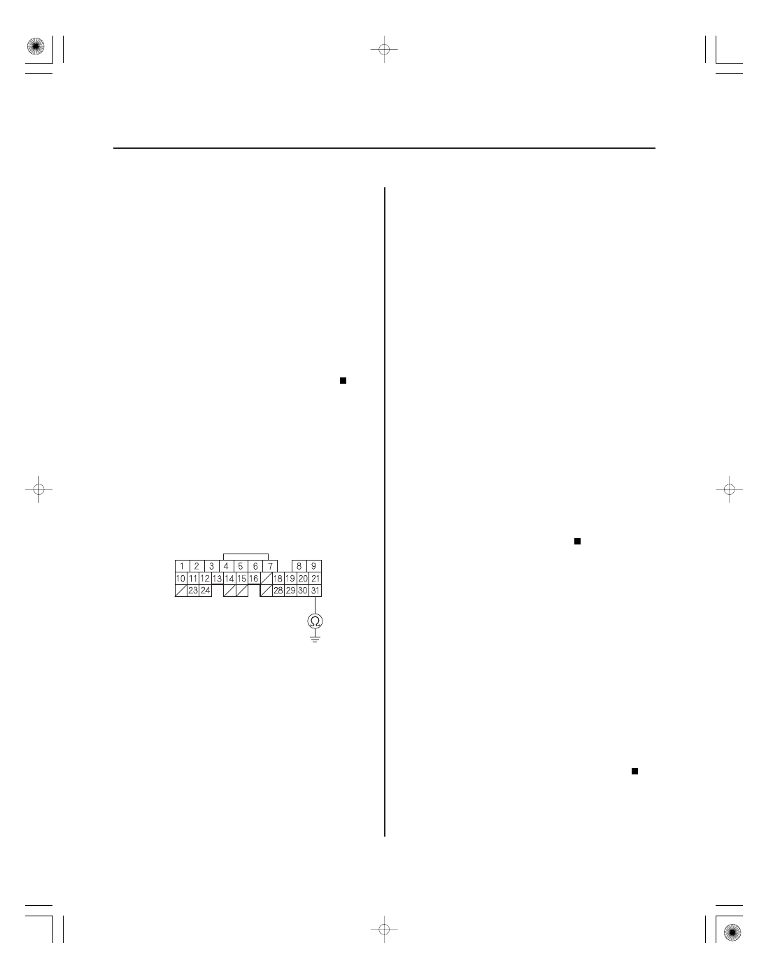
ECM/PCM CONNECTOR A (31P)
AFS
(RED)
A/F Sensor (Sensor 1) AFS
Circuit Low Voltage
(2005-2006 models)
1. Turn the ignition switch ON (II).
2. Clear the DTC with the HDS.
3. Check for Temporary DTCs or DTCs with the HDS.
Go to step 4.
Intermittent failure, system is OK at this time.
Check for poor connections or loose terminals at
the A/F sensor (Sensor 1) and the ECM/PCM.
4. Turn the ignition switch OFF.
5. Jump the SCS line with the HDS.
6. Disconnect the A/F sensor (Sensor 1) 4P connector.
7. Disconnect ECM/PCM connector A (31P).
8. Check for continuity between ECM/PCM connector
terminal A31 and body ground.
Repair short in the wire between the ECM/
PCM (A31) and the A/F sensor (Sensor 1), then go
to step 11.
Go to step 9.
9. Replace the A/F sensor (Sensor 1) (see page
11-279).
10. Reconnect all connectors.
11. Turn the ignition switch ON (II).
12. Reset the ECM/PCM with the HDS.
13. Do the ECM/PCM idle learn procedure (see page
11-349).
14. Check for Temporary DTCs or DTCs with the HDS.
If DTC P2238 is indicated, check for poor
connections or loose terminals at the A/F sensor
(Sensor 1) and the ECM/PCM. If the connector and
terminal fits are OK, go to step 16. If any other
Temporary DTCs or DTCs are indicated, go to the
indicated DTC’s troubleshooting.
Go to step 15.
15. Monitor the OBD STATUS for DTC P2238 in the
DTCs MENU with the HDS.
Troubleshooting is complete.
If the screen indicates FAILED, check for poor
connections or loose terminals at the A/F sensor
(Sensor 1) and the ECM/PCM, then go to step 1. If
the screen indicates NOT COMPLETED, go to step
13 and recheck.
16. Update the ECM/PCM if it does not have the latest
software, or substitute a known-good ECM/PCM
(see page 11-6).
17. Check for Temporary DTCs or DTCs with the HDS.
Go to step 1 and recheck.
If the ECM/PCM was updated, troubleshooting
is complete. If the ECM/PCM was substituted,
replace the original ECM/PCM (see page 11-284).
Wire side of female terminals
Is DT C P2238 indicated?
Is ther e continuity?
Ar e any T empor ar y DT Cs or DT Cs indicated?
Does the scr een indicate PASSED?
Is DT C P2238 indicated?
05/06/27 17:38:32 61S6M040_110_0242