Acura RSX Honda Integra. Manual - part 122
01
02
03
S6M6AAJK72100090563FAAT00
−
−
−
−
−
−
DTC P0563:
YES
NO
YES
NO
YES
NO
11-194
PGM-FI System
DTC Troubleshooting (cont’d)
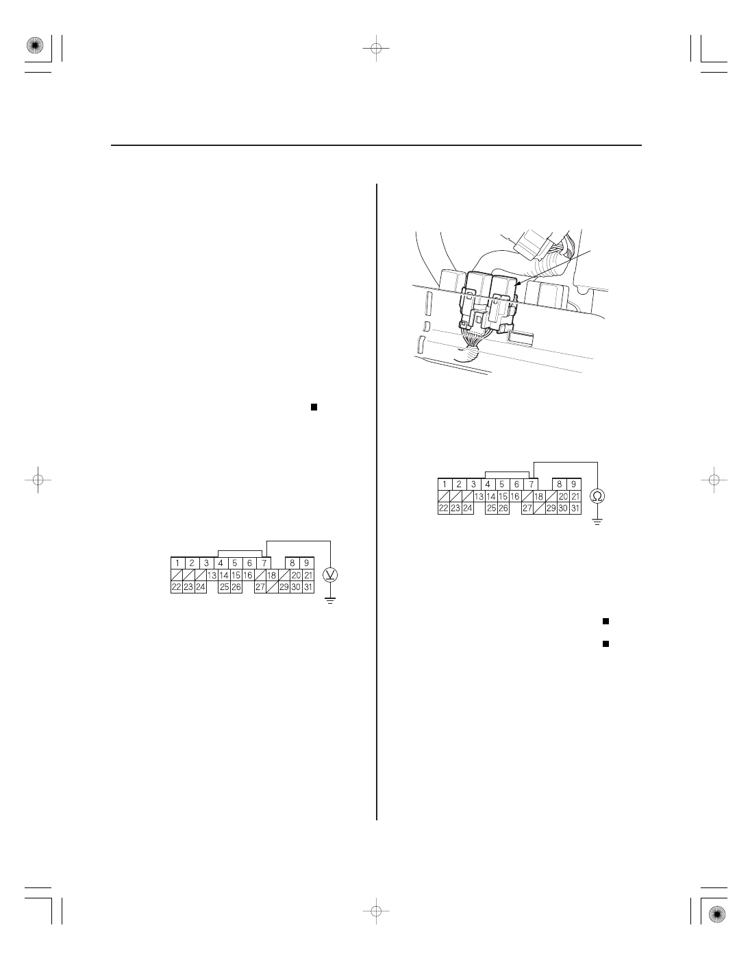
ECM/PCM CONNECTOR E (31P)
MRLY
(RED/YEL)
A
ECM/PCM CONNECTOR E (31P)
MRLY
(RED/YEL)
ECM/PCM Power Source Circuit
Unexpected Voltage
(2002-2004 models)
1. Reset the ECM/PCM (see page 11-4).
2. Turn the ignition switch OFF.
3. Wait 5 seconds.
4. Turn the ignition switch ON (II).
Go to step 5.
Intermittent failure, system is OK at this time.
Check for poor connections or loose terminals at
the No. 6 ECU (ECM/PCM) (15 A) fuse in the under-
hood fuse/relay box and the ECM/PCM.
5. Turn the ignition switch OFF.
6. Disconnect ECM/PCM connector E (31P).
7. Measure voltage between ECM/PCM connector
terminal E7 and body ground.
Go to step 11.
Go to step 8.
8. Remove the glove box (see page 20-67).
9. Remove PGM-FI main relay 1 (FI MAIN) (A).
10. Check for continuity between ECM/PCM connector
terminal E7 and body ground.
Repair short in the wire between the ECM/
PCM (E7) and PGM-FI main relay 1 (FI MAIN).
Replace PGM-FI main relay 1 (FI MAIN).
11. Reconnect ECM/PCM connector E (31P).
Wire side of female terminals
Wire side of female terminals
Is DT C P0563 indicated?
Is ther e batter y voltage?
Is ther e continuity?
05/06/27 17:35:48 61S6M040_110_0194