Acura RSX Honda Integra. Manual - part 87
25
−
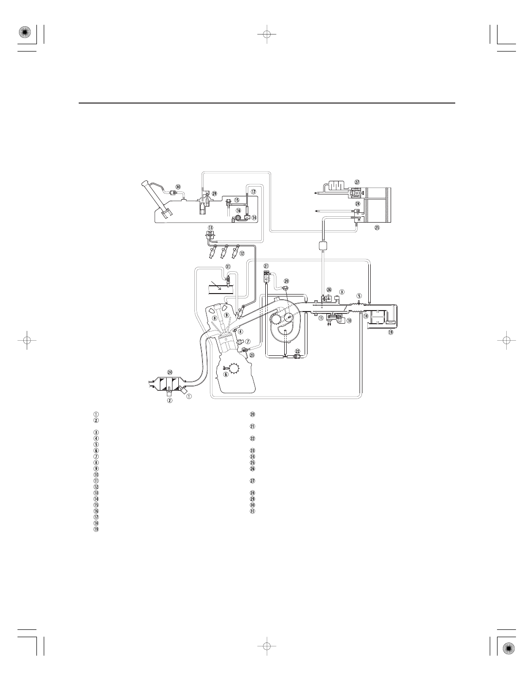
Vacuum Distribution
K20A3 engine
2005-2006 models
11-54
Fuel and Emissions Systems
System Description (cont’d)
ATMOSPHERE
ATMOSPHERE
ENGINE
COOLANT
ENGINE
COOLANT
AIR FUEL RATIO (A/F) SENSOR (SENSOR 1)
SECONDARY HEATED OXYGEN SENSOR
(SECONDARY HO2S) (SENSOR 2)
MANIFOLD ABSOLUTE PRESSURE (MAP) SENSOR
ENGINE COOLANT TEMPERATURE (ECT) SENSOR
INTAKE AIR TEMPERATURE (IAT) SENSOR
CRANKSHAFT POSITION (CKP) SENSOR
KNOCK SENSOR (KS)
CAMSHAFT POSITION (CMP) SENSOR A
CAMSHAFT POSITION (CMP) SENSOR B
IDLE AIR CONTROL (IAC) VALVE
THROTTLE BODY
INJECTOR
FUEL PULSATION DAMPER
FUEL FILTER
FUEL PRESSURE REGULATOR
FUEL PUMP
FUEL TANK
RESONATOR
AIR CLEANER
POSITIVE CRANKCASE VENTILATION (PCV) VALVE
THREE WAY CATALYTIC CONVERTER
EVAPORATIVE EMISSION (EVAP) CANISTER
EVAPORATIVE EMISSION (EVAP) CANISTER
PURGE VALVE
EVAPORATIVE EMISSION (EVAP) CANISTER
VENT SHUT VALVE
FUEL TANK PRESSURE (FTP) SENSOR
FUEL TANK VAPOR CONTROL VALVE
FUEL TANK VAPOR RECIRCULATION VALVE
INTAKE AIR BYPASS CONTROL THERMAL VALVE
INTAKE MANIFOLD TUNING (IMT)
(INTAKE MANIFOLD RUNNER CONTROL (IMRC)) ACTUATOR
INTAKE MANIFOLD TUNING (IMT)
(INTAKE MANIFOLD RUNNER CONTROL (IMRC)) SOLENOID VALVE
INTAKE MANIFOLD TUNING (IMT)
(INTAKE MANIFOLD RUNNER CONTROL (IMRC)) CHECK VALVE
05/06/27 17:32:00 61S6M040_110_0054