Turn Signal/Hazard Flasher System
Component Location Index
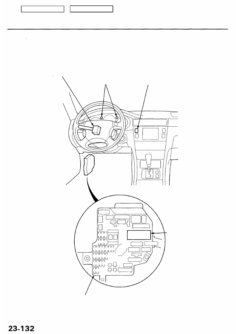
TURN SIGNAL SWITCH
Test, page
23-118
TURN SIGNAL INDICATOR
LIGHTS
(In the gauge assembly)
Bulb Locations, page
23-76
HAZARD WARNING SWITCH
Test, page
23-135
TURN SIGNAL/HAZARD
RELAY
Input Test, page
23-134
UNDER-DASH
FUSE/RELAY BOX
Main Menu
Table of Contents