Acura RL (1996-2004 year). Manual - part 590


  Index      Acura     Acura RL 1996-2004 year - service repair manual


Search            


Content   ..  588  589  590  591   ..


Acura RL (1996-2004 year). Manual - part 590


Troubleshooting

Symptom Chart

For electrical malfunctions which are indicated by the self-diagnostic system, refer to self-diagnosis function (see next
page).

NOTE:

Check the engine coolant level, and allow the engine to warm up before troubleshooting.
Any abnormality must be corrected before continuing the test.
Because of the precise measurements needed, use a multimeter when testing.
Before performing any troubleshooting procedures check:

— Fuses No. 37 (40 A), No. 47 (20 A), No. 50 (20 A), No. 56 (7.5 A) in the under-hood fuse/relay box, and No. 3 (7.5 A), No.

5 (20 A) in the under-dash fuse/relay box

— Grounds No. G201, G301, G302, G401, G402, G404
— Cleanliness and tightness of all connectors
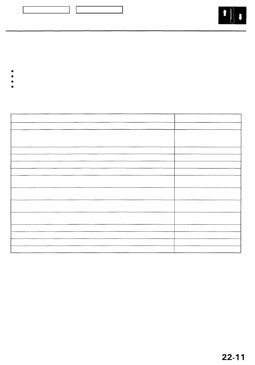
Symptom

Recirculation control doors do not change between FRESH and RECIRCULATE.

The blower motor does not run immediately even though the engine is fully warmed

up. (NOTE: The temperature control dial must be set between 61 °F [18°C] and 89°F
[32°C].)

No heater and A/C in either manual or AUTO modes.

Both fans do not run for engine cooling (but they both run with the A/C on).

Both fans always run at high speed for engine cooling.

Both fans always run at high speed with the A/C on.

Radiator fan does not run at high speed (but condenser fan runs at high speed, and
both fans run at low speed).

Condenser fan does not run at high speed (but radiator fan runs at high speed, and
both fans run at low speed).

Both fans do not run at low speed, and radiator fan does not run at high speed (but

condenser fan runs at high speed).

Both fans do not run at low speed, and condenser fan does not run at high speed
(but radiator fan runs at high speed).

Both fans do not run at low speed (but both fans run at high speed).

Both fans do not run at high speed (but both fans run at low speed).

Compressor clutch does not engage.

Both fans and compressor do not work at all.

See page

22-34

22-36

22-37

22-38

22-39

22-40

22-41

22-42

22-43

22-44

22-47

22-48

22-49

22-53

Main Menu

Table of Contents

Troubleshooting

Self-diagnosis Function

The climate control unit has a self-diagnosis function.

Running the Self-diagnosis Function

Turn the ignition switch ON (II), and after 1 minute, press both the AUTO and OFF buttons at the same time. While the but-
tons are pressed, indicator lights A, B, C, D, E, F and G respectively will come on to indicate a faulty component.

A/C

AUTO BUTTON

OFF BUTTON

A

B

C

D

E

F

G

Indicator

A/C

ON

A/C ECON

OFF

Component with problem

In-car temperature sensor

Outside air temperature sensor

Sunlight sensor

Evaporator temperature sensor

Air mix control motor

Mode control motor

Blower motor

Possible cause

Open or short circuit, faulty sensor

Open or short circuit, faulty sensor

Open or short circuit, faulty sensor

Open or short circuit, faulty sensor

Open or short circuit, obstructed door,
faulty motor

Open or short circuit, obstructed door,
faulty motor

Open or short circuit, faulty motor

See page

22-16

22-18

22-20

22-22

22-24

22-26

22-28, 22-30

NOTE: In case of multiple problems, the respective indicator lights will come on. If indicator lights A, B, C, D, E and F

come on at the same time, there may be an open in the common ground wire of the sensors.

Resetting the Self-diagnosis Function

Turning the ignition switch OFF will cancel the self-diagnosis function. After service work, run the self-diagnosis function
once again to check that there is no other problem.

Main Menu

Table of Contents

Climate Control Unit Input/Output Signals

8P CONNECTOR

CLIMATE CONTROL UNIT CONNECTORS

20P CONNECTOR

Wire side of female terminals

8P CONNECTOR

Terminal

No.

1

2

3

4

Wire Color

BLK/YEL

PNK/BLU

GRY

WHT/YEL

Signal

IG2 POWER

SENSOR GROUND

AIR MIX/MODE

POTENTIAL +5 V

BACK UP POWER

INPUT

INPUT

OUTPUT

INPUT

Terminal

No.

5

6

7

8

Wire Color

RED

RED/BLK

BLK

BLU/RED

Signal

DASH LIGHTS BRIGHT-

NESS CONTROLLER

No. 49 (7. 5 A) FUSE

GROUND

BLOWER FEEDBACK

OUTPUT

INPUT

OUTPUT

INPUT

20P CONNECTOR

Terminal

No.

1

2

3

4

5

6

7

9

10

Wire Color

ORN

BRN

BRN/WHT

BRN/BLK

BLU

LT GRN/RED

RED/YEL

RED

Signal

POWER TRANSISTOR

BASE

EVAPORATOR TEMPER-

ATURE SENSOR

OUTSIDE AIR TEMPER-

ATURE SENSOR

IN-CAR TEMPERATURE

SENSOR

MODE DEF

MODE VENT

AIR MIX HOT

AIR MIX COOL

OUTPUT

INPUT

INPUT

INPUT

OUTPUT

OUTPUT

OUTPUT

OUTPUT

Terminal

No.

11

12

14

15

16

17

18

19

20

Wire Color

LT GRN

LT GRN/BLK

PNK/BLK

WHT/RED

RED/WHT

GRN/RED

GRN/WHT

Signal

A/C PRESSURE SWITCH

BLOWER MOTOR

HIGH RELAY

MODE POTENTIAL

AIR MIX POTENTIAL

SUNLIGHT SENSOR

ENGINE COOLANT

TEMPERATURE (ECT)

SENSOR

RECIRCULATE

FRESH

INPUT

OUTPUT

INPUT

INPUT

INPUT

INPUT

OUTPUT

OUTPUT

Main Menu

Table of Contents

Troubleshooting

In-car Temperature Sensor

Self-diagnosis indicator light A comes on: A problem in the in-car temperature sensor circuit.

The in-car temperature sensor is a temperature dependent resistor (thermistor). The resistance of the thermistor decreas-

es as the temperature inside the vehicle increases.

Self-diagnosis circuit check indi-
cates a problem in the in-car

temperature sensor circuit.

Check the in-car temperature
sensor:

1. Remove the in-car temperature

sensor (see page 

22-60

), and

disconnect the 2P connector.

2. Measure the resistance

between the No. 1 and No. 2

terminals of the in-car tem-

perature sensor.

* Is the resistance within the spec-

ifications shown on the graph.

Check for a short in the wire:

1. Remove the climate control

unit (see page 

22-55

), and dis-

connect the 8P and 20P con-

nectors.

2. Check for continuity between

the No. 6 terminal of the 20P
connector and body ground.

IN-CAR TEMPERATURE SENSOR

RESISTANCE
k

14 32 50 68 86 104°F

-10 0 10 20 30 40°C

CAUTION: The sensor uses a thermistor which
can be damaged if high current is applied during

testing. Therefore, use a circuit tester with an

output of 1 mA or less at the 20 k range.

* Check for change in resistance by

heating or cooling the sensor with a
hair drier, etc.

Replace the in-car temperature
sensor.

CLIMATE CONTROL UNIT 20P CONNECTOR

Wire side of female terminals

Is there continuity?

To page 

22-17

Repair short in the wire between

the climate control unit and the

in-car temperature sensor.

Main Menu

Table of Contents


Content   ..  588  589  590  591   ..