Acura RL (1996-2004 year). Manual - part 526
DTC 31, 32, 33, 34, 35, 36, 37, 38: Solenoid
With the ignition switch ON
(II), the ABS indicator does
not go off.
With the SCS service connec-
tor connected (see page
), DTCs 31 - 38 are indi-
cated.
Problem verification:
1. Turn the ignition switch OFF,
then turn the ignition switch
ON (II) again.
2. Verify the DTC.
Is DTC 54 indicated?
Check for a short to body ground
in the solenoid:
1. Connect the modulator unit
connector.
2. Check for continuity between
the appropriate ABS control
unit 12P connector solenoid
circuit terminal and body
ground (see table).
Is there continuity?
Perform the appropriate trou-
bleshooting for DTC 54.
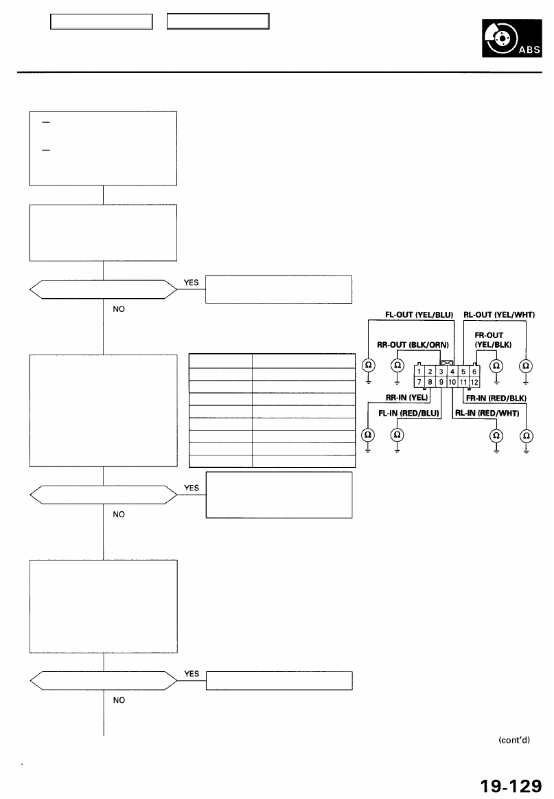
ABS CONTROL UNIT 12P CONNECTOR
DTC
31: FR-IN
32: FR-OUT
33: FL-IN
34: FL-OUT
35: RR-IN
36: RR-OUT
37: RL-IN
38: RL-OUT
Appropriate Terminal
No. 11
No. 6
No. 9
No. 4
No. 8
No. 3
No. 10
No. 5
Wire side of female terminals
Repair short to body ground in
the appropriate solenoid circuit
wire between the ABS control
unit and the modulator unit.
Replace the modulator unit.
Check for a short to body ground
in the solenoid circuit:
1. Turn the ignition switch OFF.
2. Disconnect the modulator
unit connector and the ABS
control unit 12P connector.
3. Check for continuity between
the appropriate ABS control
unit 12P connector solenoid
circuit terminal and body
ground (see table).
Is there continuity?
Main Menu
Table of Contents