Acura RL (1996-2004 year). Manual - part 423
Checking the Diagnostic Trouble Code (DTC)
with the Service Check Connector and Special Tool
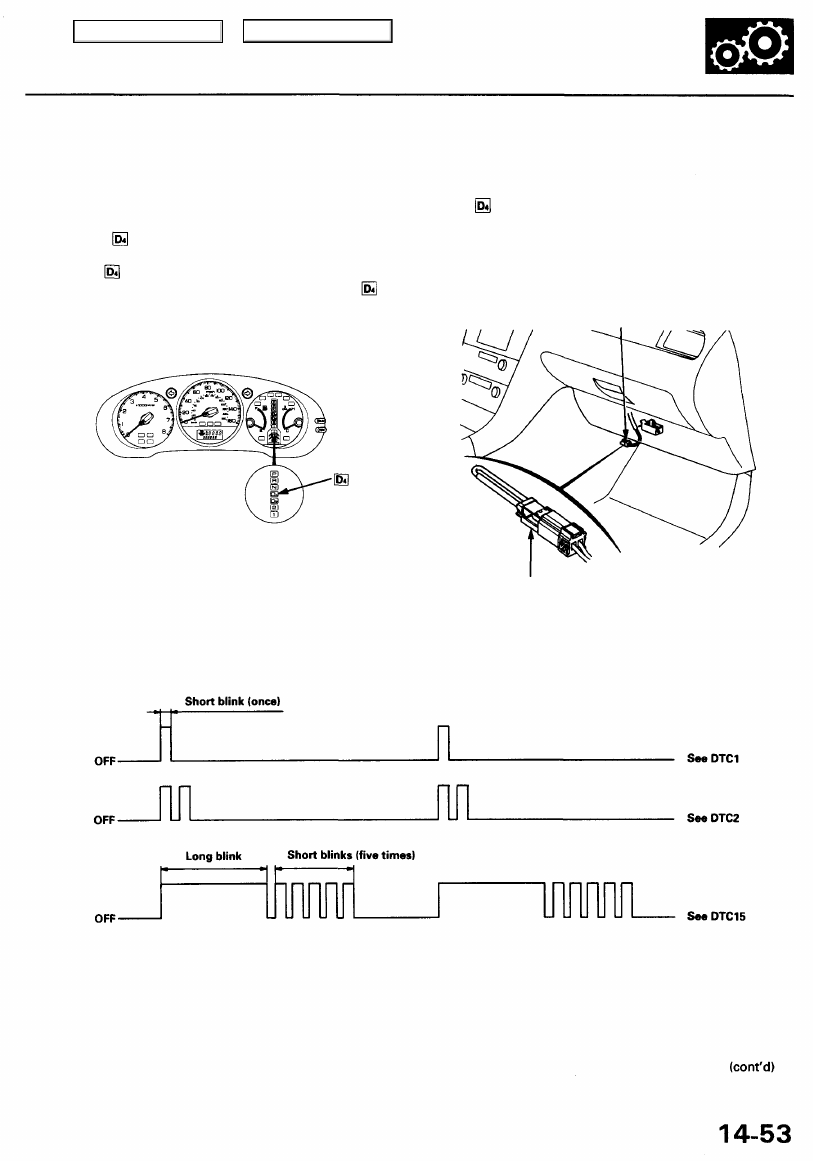
When the PCM senses an abnormality in the input or output systems, the indicator light in the gauge assembly will blink.
When the Service Check Connector (located under the dash on the passenger side) is connected with the special tool as
shown, the indicator light will blink the Diagnostic Trouble Code (DTC) when the ignition switch is turned ON (II).
When the indicator light has been reported on, connect the Service Check Connector with the special tool.
Then turn the ignition switch ON (II) and observe the indicator light.
INDICATOR
LIGHT
Codes 1 through 9 are indicated by individual short blinks. Codes 10 and above are indicated by a series of long and short
blinks. One long blink equals 10 short blinks. Add the long and short blinks together to determine the code. After deter-
mining the code, refer to the electrical system Symptom-to-Component Chart on pages
and
NOTE:
• Disconnecting the BACK UP, RADIO fuse also cancels the radio anti-theft code, preset stations and the clock setting. Get
the customer's code number, and make note of the radio presets before removing the fuse so you can reset them.
• The PCM memory must be reset after reconnecting the battery or the BACK UP, RADIO fuse (see page
SCS SERVICE CONNECTOR
GAUGE ASSEMBLY
SERVICE CHECK
CONNECTOR (2P)
Main Menu
Table of Contents