Acura RL (1996-2004 year). Manual - part 377


  Index      Acura     Acura RL 1996-2004 year - service repair manual


Search            


Content   ..  375  376  377  378   ..


Acura RL (1996-2004 year). Manual - part 377


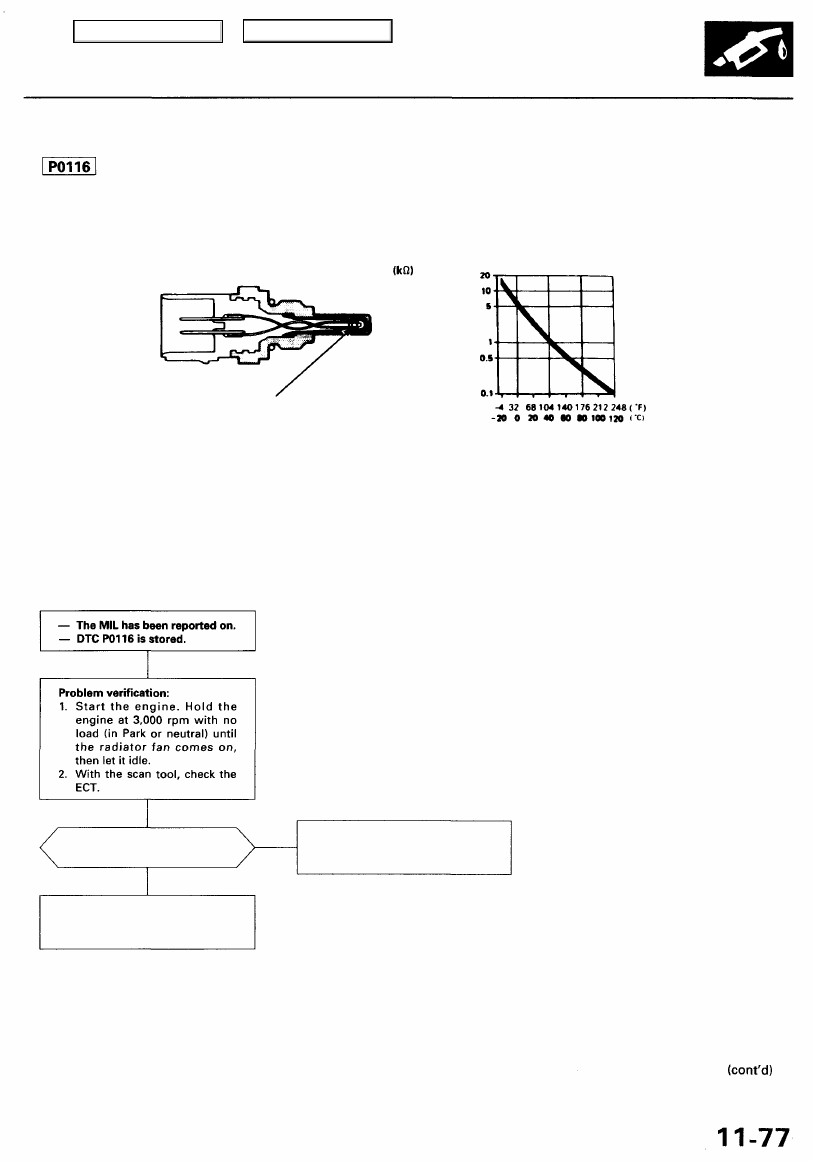
The ECT Sensor is a temperature dependent resistor (thermistor). The resistance of the thermistor decreases as the engine
coolant temperature increases as shown below.

THERMISTOR

ENGINE COOLANT TEMPERATURE

NOTE: If DTC P0117 and/or P0118 are stored at the same time as DTC P0116, troubleshoot those DTCs first, then trou-
bleshoot DTC P0116.

Possible Cause
• ECT sensor deterioration
• Malfunction in the thermostat and the cooling system

Troubleshooting Flowchart

ls176-200°F (80 - 93°C)
indicated?

Intermittent failure, system is OK
at this time. Check the thermo-
stat and the cooling system.

NO

Check the thermostat and the
cooling system. If they are OK,
replace the ECT sensor.

YES

RESISTANCE

The scan tool indicates Diagnostic Trouble Code (DTC) P0116: A range/performance problem in the Engine

Coolant Temperature (ECT) sensor circuit.

Engine Coolant Temperature (ECT) Sensor

Main Menu

Table of Contents

PGM-FI System

Engine Coolant Temperature (ECT) Sensor (cont'd)

The scan tool indicates Diagnostic Trouble Code (DTC) P0117: A low voltage (high temperature) problem in the

Engine Coolant Temperature (ECT) sensor circuit.

— The MIL has been reported on.
— DTC P0117 is stored.

Problem verification:

1. Turn the ignition switch ON (II).

2. Check the ECT with the scan

tool.

ls302°F (150°C) or higher (or
H-Limit in Honda mode of
PGM Tester) or 0 V indicated?

YES

Check for a short in the ECT sen-
sor:

1. Disconnect the ECT sensor

connector.

2. Check the ECT with the scan

tool.

ls302°F (150°C) or higher (or
H-Limit in Honda mode of
PGM Tester) or 0 V indicated?

YES

Check for a short in the wire
(ECT line):

1. Turn the ignition switch OFF.

2. Disconnect the PCM connec-

tor D (22P).

3. Check for continuity between

No. 2 terminal on the ECT

sensor connector and body
ground.

NO

Intermittent failure, system is OK
at this time. Check for poor con-
nections or loose wires at C251,
C254 (located at left shock tower),
C128 (ECT sensor), C531 (climate
control unit) and PCM.

Replace the ECT sensor.

ECT SENSOR CONNECTOR (C128)

Is there continuity?

YES

NO

Substitute a known-good PCM
and recheck (see page 

11-42 

for

immobilizer information). If nor-
mal ECT is indicated, replace the
original PCM.

Wire side of female terminals

Is there continuity?

Repair short in the wire between
PCM (D7) and ECT sensor.

Replace the climate control unit.

NO

YES

Check the climate control unit
circuits:

1. Turn the ignition switch OFF.

2. Disconnect 20P connector

from the climate control unit.

3. Check for continuity between

No. 2 terminal on the ECT

sensor connector and body
ground.

NO

Main Menu

Table of Contents

The scan tool indicates Diagnostic Trouble Code (DTC) P0118: A high voltage (low temperature) problem in the

Engine Coolant Temperature (ECT) sensor circuit.

— The MIL has been reported on.
— DTC P0118 is stored.

Problem verification:

1. Turn the ignition switch ON (II).

2. Check the ECT with the scan

tool.

Is -4°F (-20°C) or less (or L-
Limit in Honda mode of PGM
Tester) or 5 V indicated?

YES

Check for an open in the ECT sen-
sor:

1. Disconnect the ECT sensor

connector.

2. Install a jumper wire between

the two terminals on the har-

ness side of the ECT sensor

connector.

3. Check the ECT with the scan

tool.

Is -4°F (-20°C) or less (or L-
Limit in Honda mode of PGM

Tester) or 5 V indicated?

YES

Check for an open in the wires
(ECT, SG2 lines):

1. Turn the ignition switch OFF.
2. Install a jumper wire between

D7 and D22 on the PCM con-
nector.

3. Turn the ignition switch ON (II).
4. Check the ECT with the scan

tool.

Is -4°F (-20°C) or less (or L-
Limit in Honda mode of PGM

Tester) or 5 V indicated?

YES

Substitute a known-good PCM
and recheck (see page 

11-42 

for

immobilizer information). If nor-
mal ECT is indicated, replace the
original PCM.

Intermittent failure, system is OK
at this time. Check for poor con-
nections or loose wires at C251,
C254 (located at left shock tower),
C128 (ECT sensor) and PCM.

ECT SENSOR CONNECTOR (C128)

SG2
(GRN/BLU)

JUMPER WIRE

Replace the ECT sensor.

ECT
(RED/WHT)

Wire side of female terminals

Repair open in the wires between
PCM (D7, D22) and ECT sensor.

Wire side of female terminals

SG2
(GRN/BLK)

JUMPER WIRE

PCM CONNECTOR D (22P)

ECT (RED/WHT)

NO

NO

NO

Main Menu

Table of Contents

PGM-FI System

Throttle Position (TP) Sensor

The scan tool indicates Diagnostic Trouble Code (DTC) P0122: A low voltage problem in the Throttle Position

(TP) sensor circuit.

The TP Sensor is a potentiometer. It is connected to the throttle valve shaft. As the throttle position changes, the throttle

position sensor varies the voltage signal to the PCM.

— The MIL has been reported on.
— DTC P0122 is stored.

Problem verification:

1. Start the engine. Hold the

engine at 3,000 rpm with no
load (in Park or neutral) until
the radiator fan comes on,
then turn the ignition switch
OFF.

2.  Turn the ignition switch ON (II).
3. Check the throttle position

with the scan tool.

Is there approx. 10% when

the throttle is fully closed
and approx. 90% when the
throttle is fully opened?

NO

Check for an open in the wire
(VCC2 line):

1. Turn the ignition switch OFF.

2. Disconnect the TP sensor con-

nector.

3. Turn the ignition switch ON (II).
4. Measure voltage between

No. 1 terminal and No. 3 termi-
nal on the TP sensor connector.

BRUSH
HOLDER

BRUSH

RESISTOR

YES

Is there about 5 V?

NO

YES

Check for an open or short in TP
sensor:

1. Turn the ignition switch OFF.

2. Measure resistance between

No. 1 terminal and No. 2 ter-
minal on the sensor side of

TP sensor connector with the
throttle fully closed.

(To page 

11-81

)

*: with TCS
*1: with VSA

TERMINAL

INNER
BUSHING

IDLE

FULL
THROTTLE

THROTTLE
OPENING

Intermittent failure, system is OK
at this time. Check for poor con-
nections or loose wires at C113
(TP sensor) C251, C253, C254
(located at left shock tower),
C623 (TCS control unit)* C450
(VSA converter unit)*

1

 and PCM.

TP SENSOR CONNECTOR (C113)

Wire side of female terminals

Check for an open in wire (VCC2,
line):

Measure voltage between D21

terminal and D22 terminal on the

PCM connector.

Wire side of female terminals

Is there about 5 V?

Repair open in the wire between
PCM (D21) and TP sensor.

NO

Substitute a known-good PCM
and recheck (see page 

11-42 

for

immobilizer information). If pre-
scribed voltage is now available,
replace the original PCM.

Terminal side of

male terminals

YES

PCM CONNECTOR D (22P)

OUTPUT VOLTAGE (V)

Main Menu

Table of Contents


Content   ..  375  376  377  378   ..