Acura RL (1996-2004 year). Manual - part 334


  Index      Acura     Acura RL 1996-2004 year - service repair manual


Search            


Content   ..  332  333  334  335   ..


Acura RL (1996-2004 year). Manual - part 334


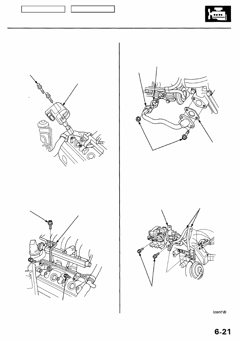
24. Remove the six ignition coils from the left and right

cylinder head covers.

6 x 1.0 mm

12 N-m (1.2 kgf-m,

8.7 Ibf-ft)

IGNITION
COIL

25. Remove the vacuum line mounting bolts from the

right cylinder head cover and intake manifold.

6 x 1.0 mm

12 N-m (1.2 kgf-m,

8.7 Ibf-ft)

VACUUM

LINE

6 x 1.0 mm
12 N-m (1.2 kgf-m, 8.7 Ibf-ft)

26. Remove the EGR pipe.

GASKET

Replace.

EGR PIPE

6 x 1.0 mm

12 N-m (1.2 kgf-m, 8.7 Ibf-ft)

GASKET
Replace.

27. Remove the vacuum hoses, then remove the Intake

Manifold Runner Control (IMRC) solenoid valve/
mount control solenoid valve assembly bracket.

BRACKET

VACUUM
HOSES

6 x 1.0 mm

12 N-m (1.2 kgf-m,

8.7 Ibf-ft)

Main Menu

Table of Contents

Cylinder Heads

Removal (cont'd)

28. Remove the wire harness holder mounting bolts.

WIRE HARNESS

HOLDER

6 x 1.0 mm

12 N-m (1.2 kgf-m, 8.7 Ibf-ft)

29. Remove the bolt securing the automatic transmis-

sion fluid (ATF) dipstick tube bracket.

30. Remove the heater hose.

6 x 1.0 mm

12 N-m (1.2 kgf-m,

8.7 Ibf-ft)

HEATER
HOSE

6 x 1.0 mm

12 N-m (1.2 kgf-m,

8.7 Ibf-ft)

31. Remove the vacuum line mounting bolts, wire har-

ness holder and positive crankcase ventilation (PCV)
hose.

PCV HOSE

VACUUM

LINE

32. Remove the EVAP canister hose, EVAP purge

solenoid valve and vacuum hose.

EVAP CONTROL
CANISTER HOSE

EVAP PURGE CONTROL
SOLENOID VALVE

6 x 1.0mm

12 N-m (1.2 kgf-m,

8.7 Ibf-ft)

VACUUM

HOSE

6 x 1.0 mm

12 N-m (1.2 kgf-m, 8.7 Ibf-ft)

6 x 1.0 mm

12 N-m (1.2 kgf-m,

8.7 Ibf-ft)

Main Menu

Table of Contents

33. Remove the TCS control valve upper and lower

brackets (see page

 6-8

).

34 Disconnect the TCS throttle position sensor connec-

tor and TCS throttle actuator connector, then remove
the TCS control valve assembly (see page 

6-8

).

35. Remove the intake manifold and water passage.

NOTE: Fill the cylinder head intake ports with clean

shop towels to prevent foreign materials from get-
ting into the cylinders.

INTAKE
MANIFOLD

WATER
PASSAGE

GASKETS
Replace.

36. Remove the covers, then remove the left and right

exhaust manifolds (see page 

9-4

).

37. Remove the balancer belt and timing belt (see page

6-8

).

38. Remove the three bolts securing the alternator

bracket.

ALTERNATOR
BRACKET

6 x 1.0 mm

12 N-m (1.2 kgf-m,

8.7 Ibf-ft)

39. Remove the two bolts securing the P/S pump bracket.

P/S PUMP
BRACKET

10 x 1.25 mm

44 N-m (4.5 kgf-m,
33 Ibf-ft)

8 x 1.25 mm

22 N-m (2.2 kgf-m,

16 Ibf-ft)

O-RING

Replace.

Main Menu

Table of Contents

Cylinder Heads

Removal (cont'd)

40. Remove the left and right camshaft pulleys, then

remove the back covers.

RIGHT
CAMSHAFT PULLEY

8 x 1.25 mm
31 N-m (3.2 kgf-m,
23 Ibf-ft)

LEFT
CAMSHAFT PULLEY

8 x 1.25 mm

31 N-m (3.2 kgf-m,
23 Ibf-ft)

BACK COVER

BACK COVER

41. Remove the left and right cylinder head covers.

6 x 1.0 mm

12 N-m (1.2 kgf-m, 8.7 Ibf-ft)

CYLINDER

HEAD COVER

42. Remove the cylinder head bolts, then remove the

cylinder heads.

CAUTION: To prevent warpage, unscrew the bolts
in sequence 1/3 turn at a time; repeat the sequence
until all bolts are loose.

CYLINDER HEAD BOLTS LOOSENING SEQUENCE:

Main Menu

Table of Contents


Content   ..  332  333  334  335   ..