Acura CSX. Manual - part 723
04
05
*01
24-208
SRS
A
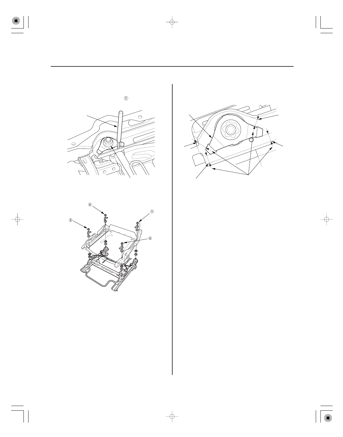
42 N·m
(4.2 kgf·m, 30 lbf·ft)
07744-0010300
MORE THAN
4 mm (0.2 in.)
A
B
B
B
B
3. Insert the special tool into the hole in the cushion
frame to position the spring washers, then tighten
the TORX nuts (A). Begin with
, and tighten them
in crisscross pattern in two or more steps.
4. Using the pin driver to position the spring washer’s,
torque the TORX nuts in the sequence shown in
two or more steps.
5. Make sure the gap between the spring washer (A)
and the seat track (B) is more than 4 mm (0.2 in.) as
shown.
6. Reassemble the front passenger’s seat cushion
cover/pad (see page 20-127).
7. Reinstall the front passenger’s seat (see page
20-118).
8. Do the battery terminal reconnection procedure
(see page 22-68).
9. Calibrate the ODS unit (see page 24-27).
10. Clear any DTCs (see page 24-23).
11. Confirm proper operation: Turn the ignition switch
to ON (II); the SRS indicator should come on for
about 6 seconds and then go off.
08/08/21 14:02:03 61SNR030_240_0208