Acura CSX. Manual - part 712
*03
09
06
−
−
−
−
YES
NO
YES
NO
24-165
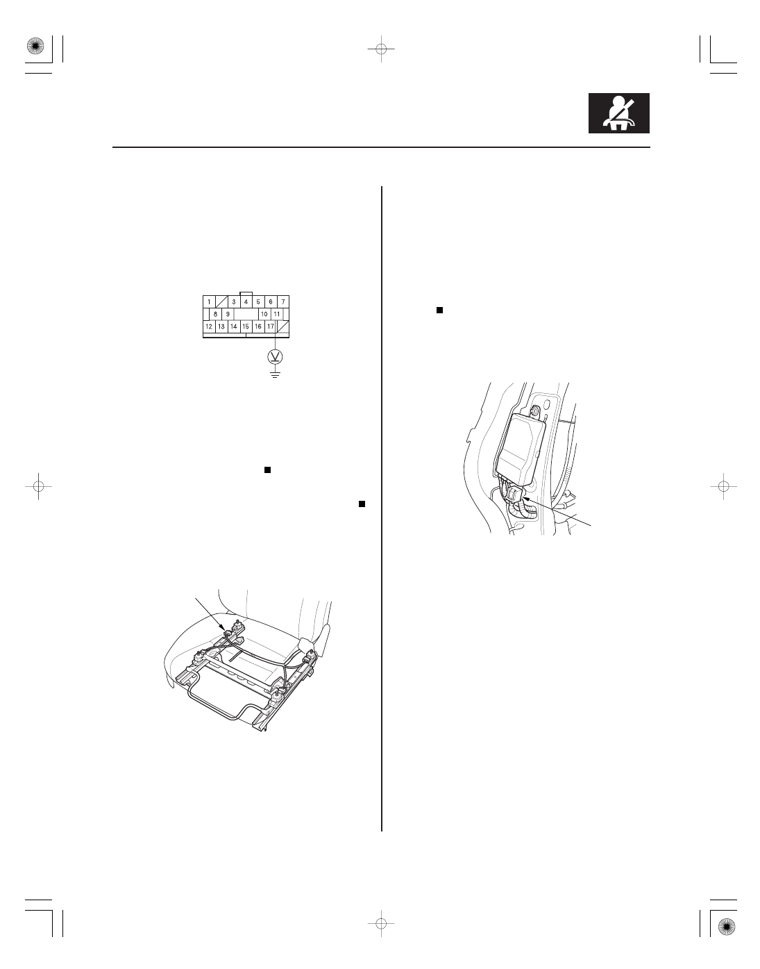
ODS UNIT HARNESS 18P CONNECTOR
BLU
A
A
17. Turn the ignition switch to ON (II).
18. Measure the voltage between ODS unit harness
18P connector terminal No. 11 and body ground.
There should be less than 0.2 V.
Replace the ODS unit harness. If the problem
is still present, replace the ODS unit (see page
24-209), then clear the DTC.
Short to power in the ODS unit harness;
replace the ODS unit harness, then clear the DTC.
19. Turn the ignition switch to LOCK (0).
20. Disconnect the ODS unit harness 3P connector (A)
from the front passenger’s weight sensor (rear
outer side).
21. Read the DTC.
Go to step 22.
Faulty front passenger’s weight sensor (rear
outer side); replace the front passenger’s seat slide
assembly including all four front passenger’s
weight sensors (see page 24-207), then clear the
DTC.
22. Turn the ignition switch to LOCK (0).
23. Disconnect the ODS unit harness 18P connector (A)
from the ODS unit.
Wire side of female terminals
Is the voltage as specif ied?
Is DT C 26-14 indicated?
08/08/21 14:00:54 61SNR030_240_0165