Acura CSX. Manual - part 414
02
03
−
−
−
−
YES
NO
YES
NO
19-161
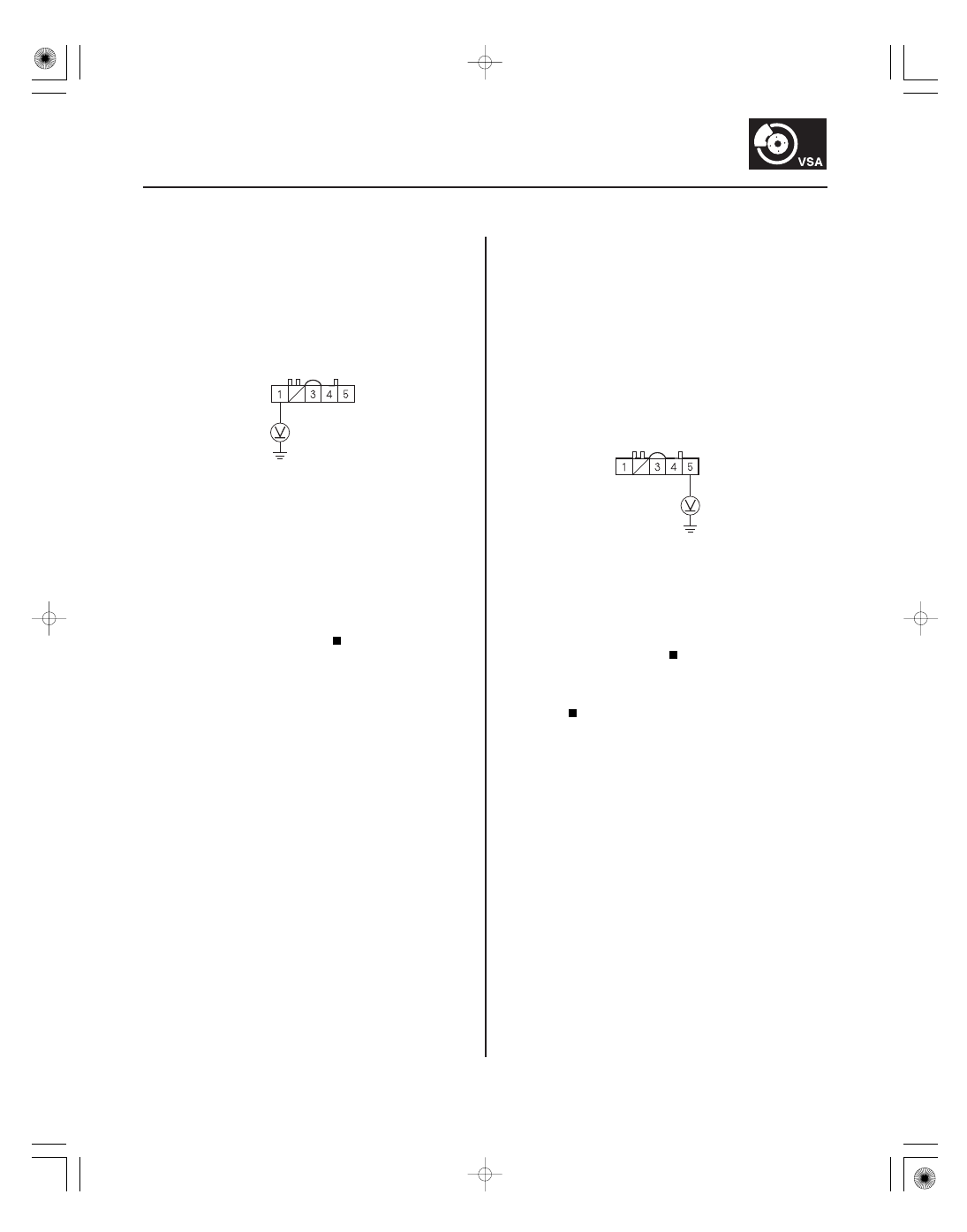
YAW RATE-LATERAL ACCELERATION SENSOR
5P CONNECTOR
YEL
YAW RATE-LATERAL ACCELERATION SENSOR
5P CONNECTOR
BLK
9. Turn the ignition switch to ON (II).
10. Measure the voltage between yaw rate-lateral
acceleration sensor 5P connector terminal No. 1
and body ground.
Go to step 11.
Check the No. 4 (7.5 A) fuse in the under-dash
fuse/relay box. If the fuse is OK, repair open in the
wire between the No. 4 (7.5 A) fuse and yaw rate-
lateral acceleration sensor.
11. Turn the ignition switch to LOCK (0).
12. Reconnect the yaw rate-lateral acceleration sensor
5P connector.
13. Turn the ignition switch to ON (II).
14. Measure the voltage between yaw rate-lateral
acceleration sensor 5P connector terminal No. 5
and body ground.
Replace the yaw rate-lateral acceleration
sensor (see page 19-169).
Repair open in the wire between the yaw rate-
lateral acceleration sensor and body ground
(G602).
Wire side of female terminals
Wire side of female terminals
Is ther e batter y voltage?
Is ther e 0.1 V or less?
08/08/21 15:06:43 61SNR030_190_0161