Acura CSX. Manual - part 410
01
SNR9AC7K801000R6412FAAT00
−
−
−
−
YES
NO
YES
NO
DTC 64-12:
19-145
19-145
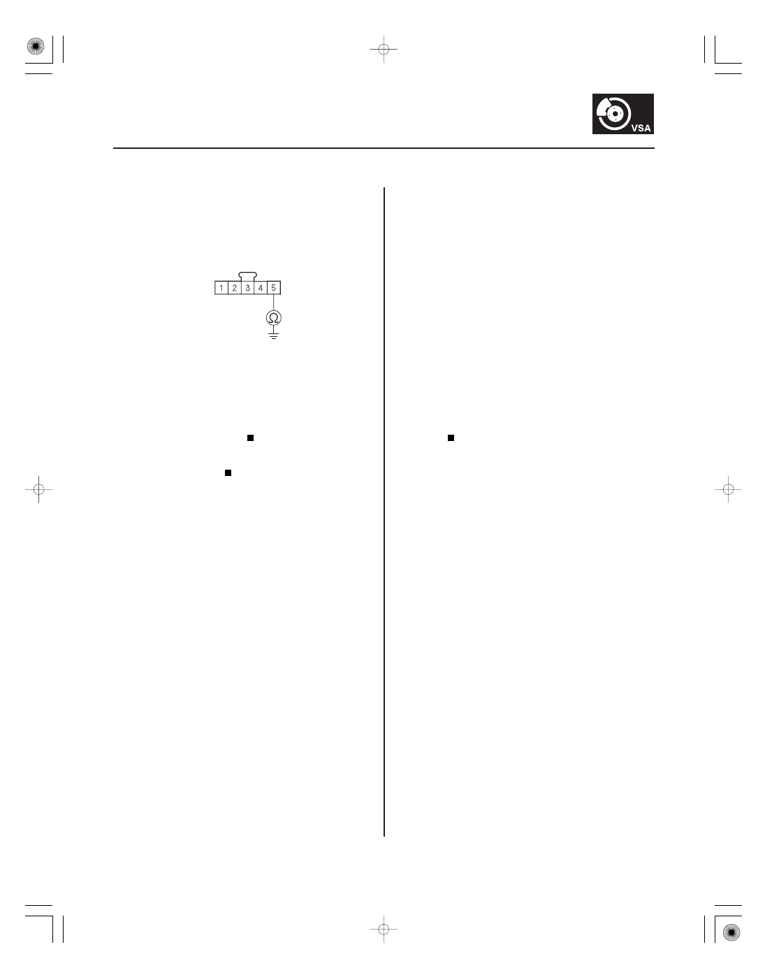
STEERING ANGLE SENSOR 5P CONNECTOR
SVCC (ORN)
8. Check for continuity between steering angle sensor
5P connector terminal No. 5 and body ground.
Repair short to body ground in the wire
between the steering angle sensor and the VSA
modulator-control unit.
Replace the VSA modulator-control unit
(see page 19-171).
1. Turn the ignition switch to ON (II).
2. Clear the DTC with the HDS.
3. Turn the ignition switch to LOCK (0), then turn it to
ON (II) again.
4. Check for DTCs with the HDS.
Go to step 5.
Intermittent failure, the system is OK at this
time. Check for loose terminals between the
steering angle sensor 5P connector and the VSA
modulator-control unit 37P connector. Refer to
intermittent failures troubleshooting (see page
19-98).
5. Turn the ignition switch to LOCK (0).
6. Disconnect the steering angle sensor 5P connector.
7. Disconnect the VSA modulator-control unit 37P
connector (see step 2 on page 19-171).
Steering Angle Sensor Power
Circuit Open
Wire side of female terminals
Is ther e continuity?
Is DT C 64-12 indicated?
08/08/21 15:05:57 61SNR030_190_0145