Acura CSX. Manual - part 369
04
System Communication
18-60
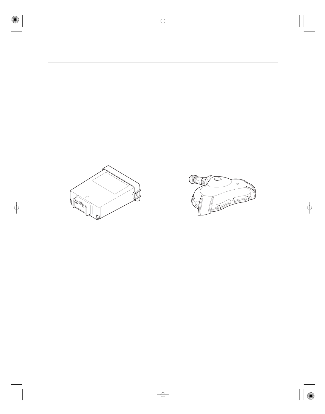
TPMS
Control Unit
(With Radio Frequecy Antenna)
Tire Pressure Sensor
(Sensor-transmitter with acceleration sensor)
• When the vehicle is traveling more than 45 km/h (28 mph), an RF (radio frequency) band wave signal is transmitted
from each tire pressure sensor to the control unit.
• When the wheels rotate, and the tire pressure sensors momentum is detected, switching them from sleep mode to
normal function (awake) mode. After the vehicle is stationary for 5 minutes, the sensors switch from normal
function mode back to sleep mode to extend their battery life.
• Each tire pressure sensor has its own ID to prevent jamming by similar systems on other vehicles. After memorizing
all the sensor IDs, the control unit recognizes only those specific signals.
• An ID cannot be memorized automatically. The control unit knows which ID belongs to each tire pressure sensor.
This recurring ID confirmation prevents any confusion in the system as a result of normal tire rotation.
NOTE: Be careful not to bend the brackets on the TPMS control unit: Misalignment of the control unit could interfere
with sending and receiving signals.
08/08/21 14:58:25 61SNR030_180_0060