Acura CSX. Manual - part 258
07
05
−
−
−
−
YES
NO
YES
NO
14-113
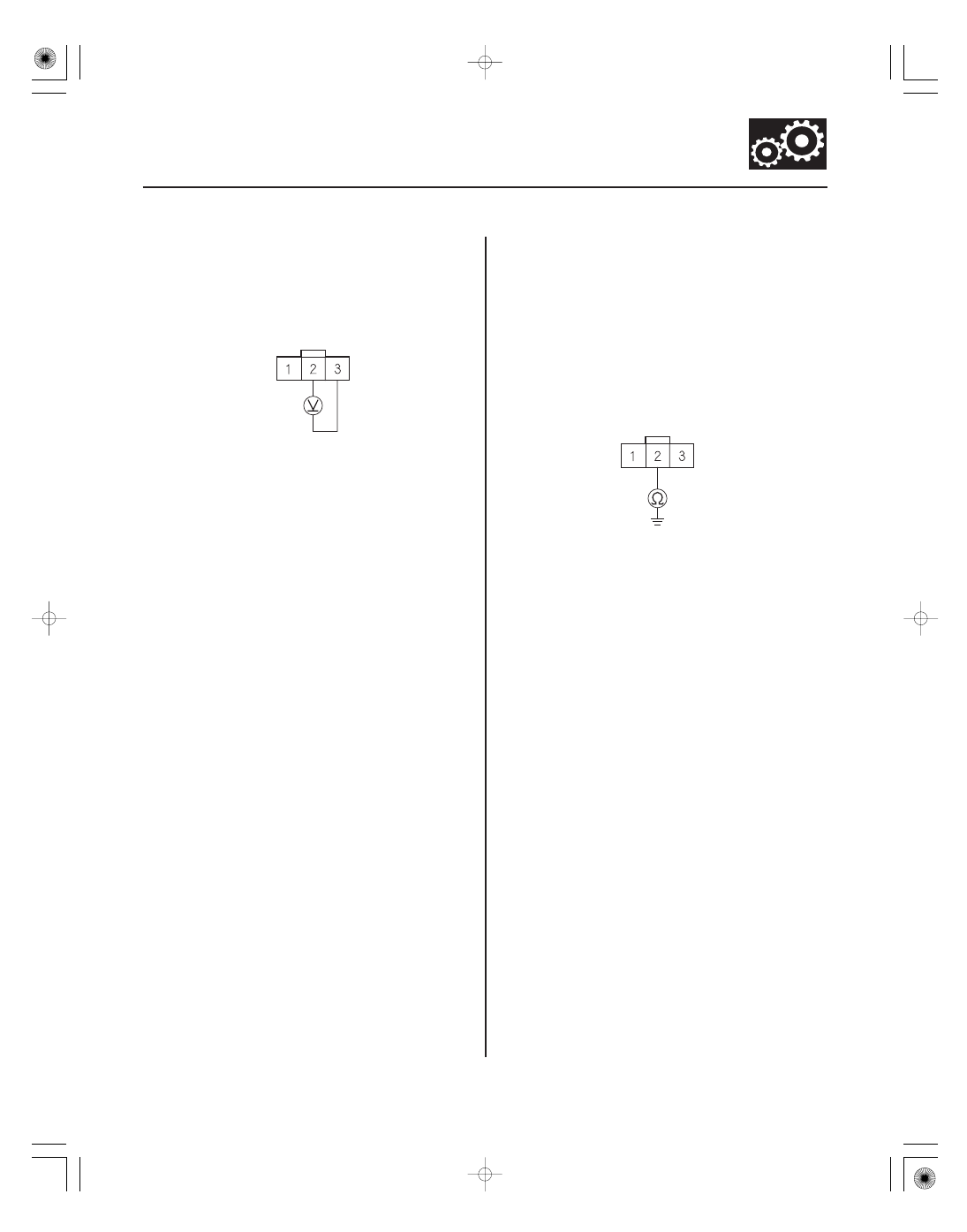
OUTPUT SHAFT (COUNTERSHAFT)
SPEED SENSOR CONNECTOR
NC (BLK/WHT)
SG1 (GRN/WHT)
OUTPUT SHAFT (COUNTERSHAFT)
SPEED SENSOR CONNECTOR
NC (BLK/WHT)
19. Measure the voltage between output shaft
(countershaft) speed sensor connector terminals
No. 2 and No. 3.
Replace the output shaft (countershaft)
speed sensor (see page 14-227), then go to step 26.
Go to step 20.
20. Turn the ignition switch to LOCK (0).
21. Jump the SCS line with the HDS.
22. Disconnect PCM connector C (44P).
23. Check for continuity between output shaft
(countershaft) speed sensor connector terminal
No. 2 and body ground.
Repair short to body ground in the wire
between PCM connector terminal C43 and the
output shaft (countershaft) speed sensor, then go
to step 26.
Go to step 24.
Wire side of female terminals
Wire side of female terminals
Is ther e about 5 V ?
Is ther e continuity?
08/08/21 14:41:08 61SNR030_140_0115