Acura CSX. Manual - part 251
*03
*04
−
−
−
−
YES
NO
YES
NO
14-85
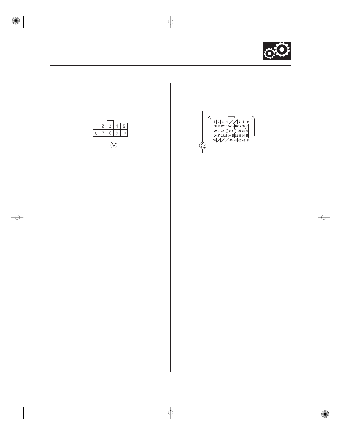
ATPR (WHT)
GND (BLK)
TRANSMISSION RANGE
SWITCH CONNECTOR
PCM CONNECTOR B (44P)
ATPR (WHT)
15. Measure the voltage between transmission range
switch connector terminals No. 7 and No. 10.
Go to step 20.
Go to step 16.
16. Turn the ignition switch to LOCK (0).
17. Jump the SCS line with the HDS.
18. Disconnect PCM connector B (44P).
19. Check for continuity between PCM connector
terminal B14 and body ground.
Repair short to body ground in the wire
between PCM connector terminal B14 and the
transmission range switch, then go to step 45.
Go to step 52.
Wire side of female terminals
Terminal side of female terminals
Is ther e mor e than 5 V ?
Is ther e continuity?
08/08/21 14:39:49 61SNR030_140_0087