Acura CSX. Manual - part 131
−
−
21
11
−
−
−
−
YES
NO
YES
NO
11-198
PGM-FI System
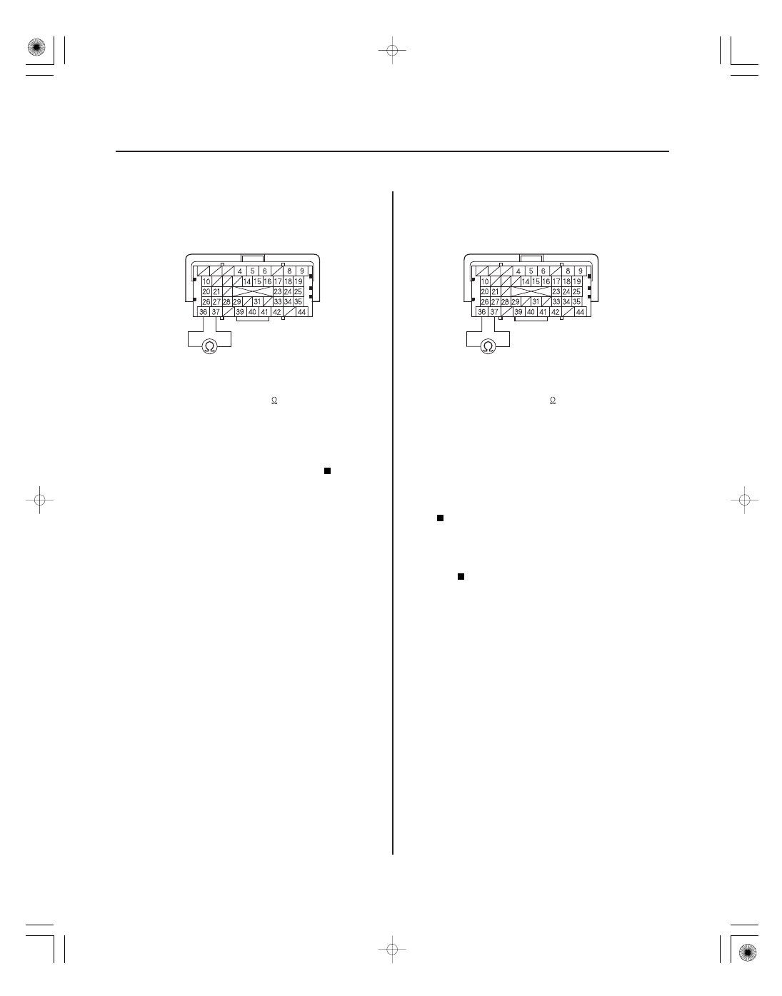
ECM/PCM CONNECTOR A (44P)
CANL (RED)
CANH (WHT)
ECM/PCM CONNECTOR A (44P)
CANL (RED)
CANH (WHT)
34. Measure the resistance between ECM/PCM
connector terminals A36 and A37.
Go to step 35.
Substitute a known-good SRS unit (see page
24-203). If the HDS identifies the vehicle, replace
the original SRS unit (see page 24-203).
35. Disconnect SRS unit connector A (28P).
36. Reconnect EPS control unit connector D (28P).
37. Measure the resistance between ECM/PCM
connector terminals A36 and A37.
• With TPMS: Go to step 38.
• Without TPMS: Update the ECM/PCM if it does
not have the latest software (see page 11-227), or
substitute a known-good ECM/PCM (see page
11-7), then recheck. If the symptom/indication
goes away with a known-good ECM/PCM,
replace the original ECM/PCM (see page 11-228).
Substitute a known-good EPS control unit
(see page 17-84). If the HDS identifies the vehicle,
replace the original EPS control unit (see page
17-84).
Terminal side of female terminals
Terminal side of female terminals
Is ther e about 2.34
2.86 k
?
Is ther e about 2.34
2.86 k
?
08/08/21 14:21:52 61SNR030_110_0198