Acura CSX. Manual - part 119
*01
04
05
−
−
−
−
YES
NO
YES
NO
11-150
PGM-FI System
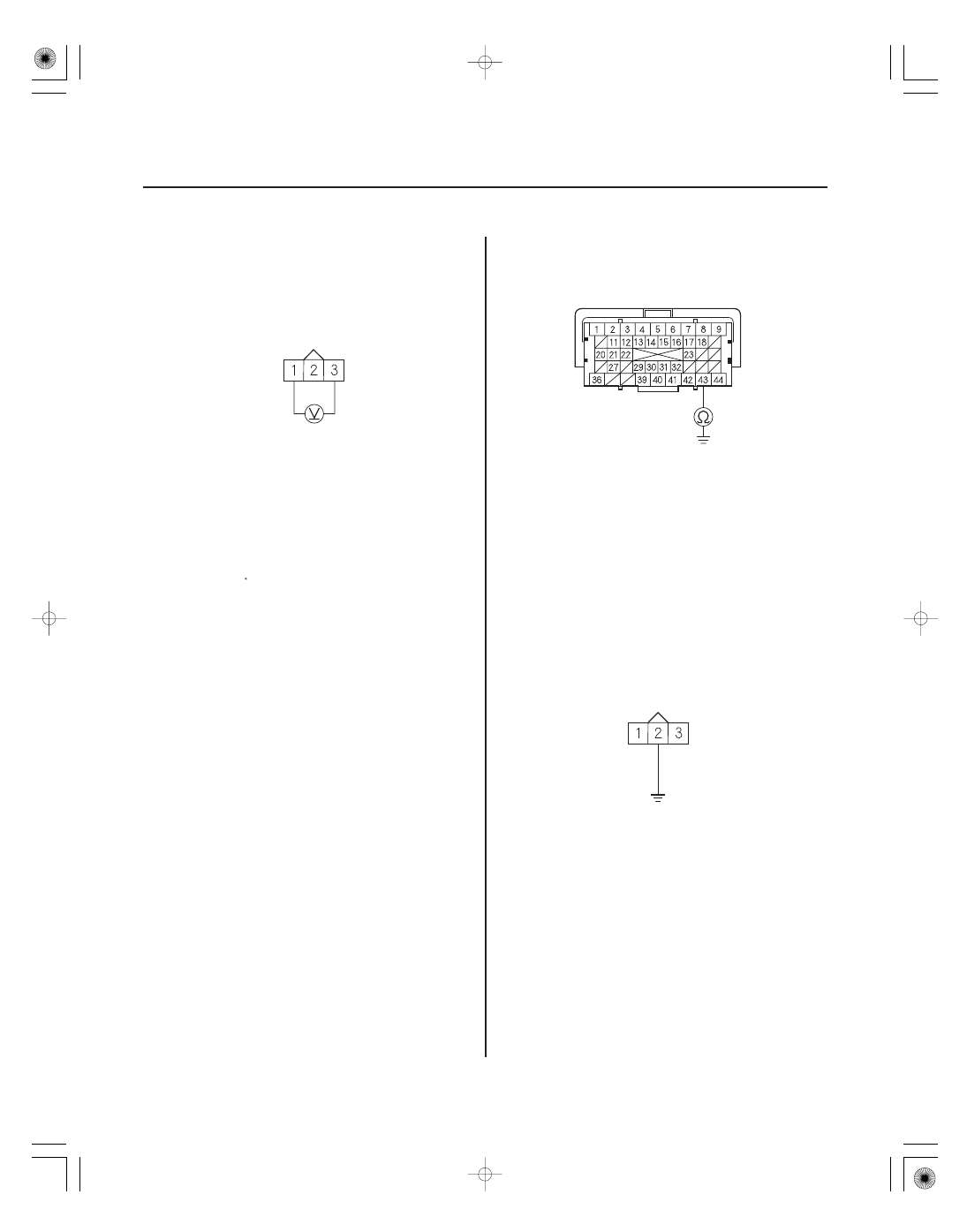
OUTPUT SHAFT (COUNTERSHAFT)
SPEED SENSOR 3P CONNECTOR
SG1 (GRN/WHT)
(SG2 (GRN/BLK))*
VCC1 (YEL/RED)
(VCC2 (YEL))*
ECM CONNECTOR C (44P)
NC (BLK/WHT)
OUTPUT SHAFT (COUNTERSHAFT)
SPEED SENSOR 3P CONNECTOR
NC (BLK/WHT)
JUMPER WIRE
9. Measure the voltage between output shaft
(countershaft) speed sensor 3P connector terminals
No. 1 and No. 3.
Go to step 16.
Repair open in the wire between the ECM
(C14) (B33) and the output shaft (countershaft)
speed sensor, then go to step 18.
10. Turn the ignition switch to LOCK (0).
11. Jump the SCS line with the HDS.
12. Disconnect ECM connector C (44P).
13. Check for continuity between ECM connector
terminal C43 and body ground.
Repair short in the wire between the ECM
(C43) and the output shaft (countershaft) speed
sensor, then go to step 18.
Go to step 14.
14. Connect output shaft (countershaft) speed sensor
3P connector terminal No. 2 to body ground with a
jumper wire.
Wire side of female terminals
Terminal side of female terminals
Wire side of female terminals
Is ther e about 5 V ?
Is ther e continuity?
08/08/21 14:19:00 61SNR030_110_0150