Acura CSX. Manual - part 112
05
−
−
−
−
−
−
YES
NO
YES
NO
PROBLEM
CYLINDER
DTC
ECM/PCM
TERMINAL
WIRE
COLOR
YES
NO
11-122
PGM-FI System
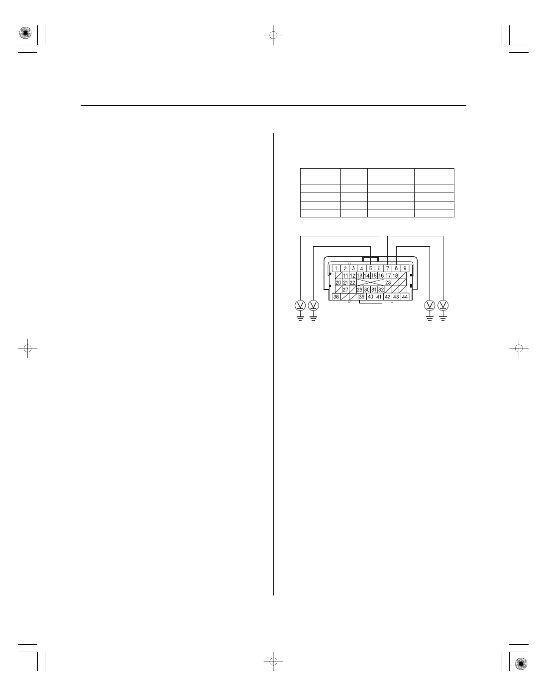
ECM/PCM CONNECTOR C (44P)
INJ4 (YEL)
INJ1 (BRN)
INJ2 (RED)
INJ3 (BLU)
39. Reconnect all connectors.
40. Do an engine compression and a cylinder leakdown
test (see page 6-7).
Go to step 41.
Repair the engine, then go to step 60.
41. Do the VTEC rocker arm test; K20Z2 engine
(see page 6-8), K20Z3 engine (see page 6-9).
Go to step 42.
Repair the VTEC rocker arm; K20Z2 engine
(see page 6-46), K20Z3 engine (see page 6-47), then
go to step 60.
42. Turn the ignition switch to LOCK (0).
43. Jump the SCS line with the HDS.
44. Disconnect ECM/PCM connector C (44P).
45. Turn the ignition switch to ON (II).
46. Measure the voltage between body ground and the
appropriate ECM/PCM connector terminal of the
problem cylinder (see table).
No. 1
P0301
C5
BRN
No. 2
P0302
C6
RED
No. 3
P0303
C7
BLU
No. 4
P0304
C8
YEL
Go to step 54.
Go to step 47.
Terminal side of female terminals
Did the engine pass both tests?
Did the engine pass the test?
Is ther e batter y voltage?
08/08/21 14:18:51 61SNR030_110_0122