Acura CSX. Manual - part 60


  Index      Acura     Acura CSX - P/NO. 61SNR03 - service repair manual 2006-2009 year


Search            


Content   ..  58  59  60  61   ..


Acura CSX. Manual - part 60


02

*01

Piston Ring End-Gap

Top Ring:
Standard (New): 0.20

0.35 mm

(0.008

0.014 in.)

Service Limit:

0.60 mm (0.024 in.)

Second Ring:
K20Z2 engine:
Standard (New): 0.40

0.55 mm

(0.016

0.022 in.)

Service Limit:

0.70 mm (0.028 in.)

K20Z3 engine:
Standard (New): 0.50

0.65 mm

(0.020

0.026 in.)

Service Limit:

0.75 mm (0.030 in.)

Oil Ring:
Standard (New): 0.20

0.70 mm

(0.008

0.028 in.)

Service Limit:

0.80 mm (0.031 in.)

7-22

Engine Block

A

B

15

20 mm (0.6

0.8 in.)

A

B

K20Z2 engine:

A

B

K20Z3 engine:

B

Top Ring (Standard):
A: 3.1 mm (0.12 in.)
B: 1.2 mm (0.05 in.)

Second Ring (Standard):
A: 3.4 mm (0.13 in.)
B: 1.2 mm (0.05 in.)

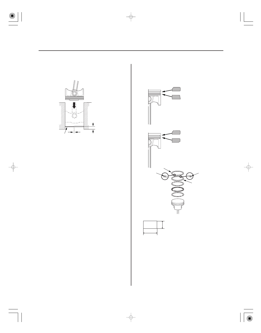
Piston Ring Dimensions

A

A

B

C

C

4. Using a piston that has its rings removed, push a

new ring (A) into the cylinder bore 15

20 mm

(0.6

0.8 in.) from the bottom.

5. Measure the piston ring end-gap (B) with a feeler

gauge:

• If the gap is too small, check to see if you have

the proper rings for your engine.

• If the gap is too large, recheck the cylinder bore

diameter against the wear limits (see page 7-16).
If the bore is beyond the service limit, the engine
block must be rebored.

6. Install the top ring and the second ring as shown.

The top ring (A) has a 1R mark, and the second ring
(B) has a 2R mark. The manufacturing marks (C)
must be facing upward.

05

04

*01

02

SNR9A00A18360200000KCAT00

Top Ring Clearance
K20Z2 engine:
Standard (New): 0.035

0.060 mm

(0.0014

0.0024 in.)

Service Limit:

0.13 mm (0.005 in.)

K20Z3 engine:
Standard (New): 0.045

0.070 mm

(0.0018

0.0028 in.)

Service Limit:

0.13 mm (0.005 in.)

Second Ring Clearance
K20Z2 engine:
Standard (New): 0.030

0.055 mm

(0.0012

0.0022 in.)

Service Limit:

0.13 mm (0.005 in.)

K20Z3 engine:
Standard (New): 0.040

0.065 mm

(0.0016

0.0026 in.)

Service Limit:

0.13 mm (0.005 in.)

If the Crankshaft is Already Installed

7-23

7-23

Piston Installation

OIL RING GAP

About 90 °

SECOND RING GAP

PISTON PIN

OIL RING GAP

About 45 °

TOP RING GAP and
SPACER RING GAP

A

A

B

7. After installing a new set of rings, measure the

ring-to-groove clearances:

8. Rotate the rings in their grooves to make sure they

do not bind.

9. Position the ring end gaps as shown:

1. Set the crankshaft to bottom dead center (BDC) for

each cylinder as its piston is installed.

2. Remove the connecting rod caps, then install the

ring compressor. Check that the bearing is securely
in place.

3. Apply new engine oil to the piston, inside of the

ring compressor, and the cylinder bore, then attach
the ring compressor to the piston/connecting rod
assembly.

4. Position the mark (A) to face the cam chain side of

the engine block.

5. Position the piston/connecting rod assembly in the

cylinder, and tap it in using the wooden handle of a
hammer (A).
Push down on the ring compressor (B) to prevent
the rings from expanding before entering the
cylinder bore.

6. Stop after the ring compressor pops free, and

check the connecting rod-to-rod journal alignment
before pushing the piston into place.

This illustration shows K20Z2 engine.

03

*02

05

If the Crankshaft is Not Installed

7-24

Engine Block

90 °

A

A

B

7. Check the connecting rod bearing clearance with

plastigage (see page 7-8).

8. Inspect the connecting rod bolts (see page 7-25).

9. Install the rod caps with bearings. Tighten the bolts

to 20 N·m (2.0 kgf·m, 14 lbf·ft) (K20Z2 engine) or
29 N·m (3.0 kgf·m, 22 lbf·ft) (K20Z3 engine).

NOTE: Apply new engine oil to the bolt threads and
flanges.

10. Tighten the connecting rod bolts an additional 90 °.

NOTE: Remove the connecting rod bolt if you
tightened it beyond the specified angle, and go
back to step 8 of the procedure. Do not loosen it
back to the specified angle.

1. Remove the connecting rod caps, then install the

ring compressor, and check that the bearing is
securely in place.

2. Apply new engine oil to the piston, inside of the

ring compressor, and the cylinder bore, then attach
the ring compressor to the piston/connecting rod
assembly.

3. Position the mark (A) to face the cam chain side of

the engine block.

4. Position the piston/connecting rod assembly in the

cylinder, and tap it in using the wooden handle of a
hammer (A).
Push down on the ring compressor (B) to prevent
the rings from expanding before entering the
cylinder bore.

5. Position all pistons at top dead center (TDC).

This illustration shows K20Z2 engine.


Content   ..  58  59  60  61   ..