Acura CSX. Manual - part 57


  Index      Acura     Acura CSX - P/NO. 61SNR03 - service repair manual 2006-2009 year


Search            


Content   ..  55  56  57  58   ..


Acura CSX. Manual - part 57


01

02

SNR9A00A18300043401KAAT00

7-11

Oil Pan Removal

1. If the engine is already out of the vehicle, go to step

18.

2. Raise the vehicle on the lift.

3. Drain the engine oil (see page 8-10).

4. Remove the front wheels.

5. Remove the splash shield (see step 25 on page 5-5).

6. Separate the stabilizer links (see page 18-25).

7. Separate the knuckles from the lower arms (see

step 6 on page 18-21).

8. Remove the steering gearbox bracket. Remove the

steering gearbox mounting bolt, the stiffener
mounting bolt, and the stiffener (see step 36 on
page 5-6).

9. Remove the steering gearbox mounting bolt, the

stiffener mounting bolt, and the stiffener. Remove
the harness clamp from the front subframe (see
step 38 on page 5-6).

10. A/T model: Remove the bolt securing the automatic

transmission fluid (ATF) filter.

11. Install the front leg assembly, the hook, and the

wing nut to an A and Reds engine support hanger
(AAR-T1256) onto the 2006 Civic engine hanger
(VSB02C000025). Carefully position the engine
hanger on the vehicle, and attach the hook to the
slotted hole in the support eyelet. Tighten the wing
nut by hand to lift and support the engine/
transmission (see step 47 on page 5-8).

12. Remove the lower torque rod (see step 49 on page

5-8).

13. M/T model: Remove the front mount mounting bolt

(see step 50 on page 5-9).

14. Make the appropriate reference line at both sides of

the front subframe that line up with the edges on
the body (see step 51 on page 5-9).

15. Loosen the mid-stiffener mounting bolts on both

sides (see step 52 on page 5-9).

16. Attach the front subframe adapter (VSB02C000016)

to the front subframe, and hang the belt of the front
subframe adapter over the front of the subframe.
Secure the belt with its stop, then tighten the wing
nut (see step 53 on page 5-9).

17. Remove the front subframe (see step 55 on page

5-10).

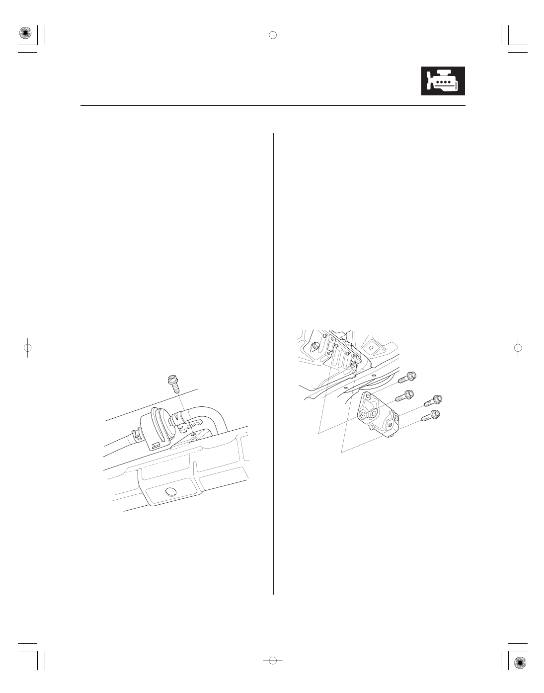
18. Remove the lower torque rod bracket.

03

04

01

05

7-12

Engine Block

B

A

19. A/T model: Remove the shift cable cover.

20. K20Z2 engine: Remove the torque converter cover/

clutch cover.

21. K20Z3 engine: Remove the clutch cover (A) and the

transmission mounting bolts (B).

22. Remove the bolts securing the oil pan.

23. Using a flat blade screwdriver, separate the oil pan

from the lower block in the places shown.

24. Remove the oil pan.

01

02

03

SNR9A00A18316600000KAAT20

7-13

Crankshaft and Piston Removal

1. Remove the engine/transmission (see page 5-3).

2. Remove the transmission:

• Manual transmission (see page 13-7)
• Automatic transmission (see page 14-233)

3. M/T model: Remove the pressure plate (see page

12-19), the clutch disc (see page 12-20), and the
flywheel (see page 12-21).

4. A/T model: Remove the drive plate (see page

14-242).

5. Remove the oil pan (see page 7-11).

6. Remove the oil pump (see page 8-16).

7. Remove the cylinder head (see page 6-38).

8. Remove the baffle plates.

9. Remove the 8 mm bolts in sequence.

10. Remove the bearing cap bolts. To prevent warpage,

loosen the bolts in sequence 1/3 turn at a time;
repeat the sequence until all bolts are loosened.

04

05

06

07

7-14

Engine Block

A

A

B

11. Remove the lower block and the bearings. Keep all

the bearings in order.

12. Remove the connecting rod caps/bearing halves.

Keep all connecting rod caps/bearing halves in
order.

13. Lift the crankshaft out of the engine. Be careful not

to damage the journals.

14. Remove the upper bearing halves from the

connecting rods, and set them aside with their
respective caps.

15. If you can feel a ridge of metal or hard carbon

around the top of each cylinder, remove it with a
ridge reamer (A). Follow the reamer manufacturer’s
instructions. If the ridge is not removed, it may
damage the pistons as they are pushed out.

16. Use the wooden handle of a hammer (A) to drive

out the piston/connecting rod assembly (B).

17. Reinstall the lower block and the bearings on the

engine in the proper order.

18. Reinstall the connecting rod bearings and the caps

after removing each piston/connecting rod
assembly.

19. Mark each piston/connecting rod assembly with its

cylinder number to make sure they are reused in
the original order.

NOTE: The existing number on the connecting rod
does not indicate its position in the engine, it
indicates the rod bore size.


Content   ..  55  56  57  58   ..