Acura CSX. Manual - part 43
13
*02
15
16
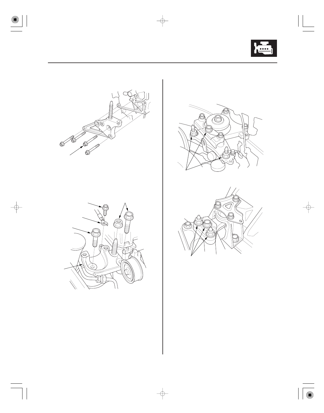
M/T model
A/T model
6-25
10 x 1.25 mm
44 N·m
(4.5 kgf·m, 33 lbf·ft)
D
A
C
B
6 x 1.0 mm
10 N·m
(1.0 kgf·m, 7.2 lbf·ft)
A
A
21. Install the side engine mount bracket.
22. Install the side engine mount bracket (A), then
loosely tighten the new bolt and nut (B), and
loosely tighten the bolt (C).
23. Install the ground cable (D).
24. Remove the air cleaner assembly (see page 11-345).
25. Loosen the transmission mounting bolt and nuts
(A).
Replace.