Acura CSX. Manual - part 38
*04
6-6
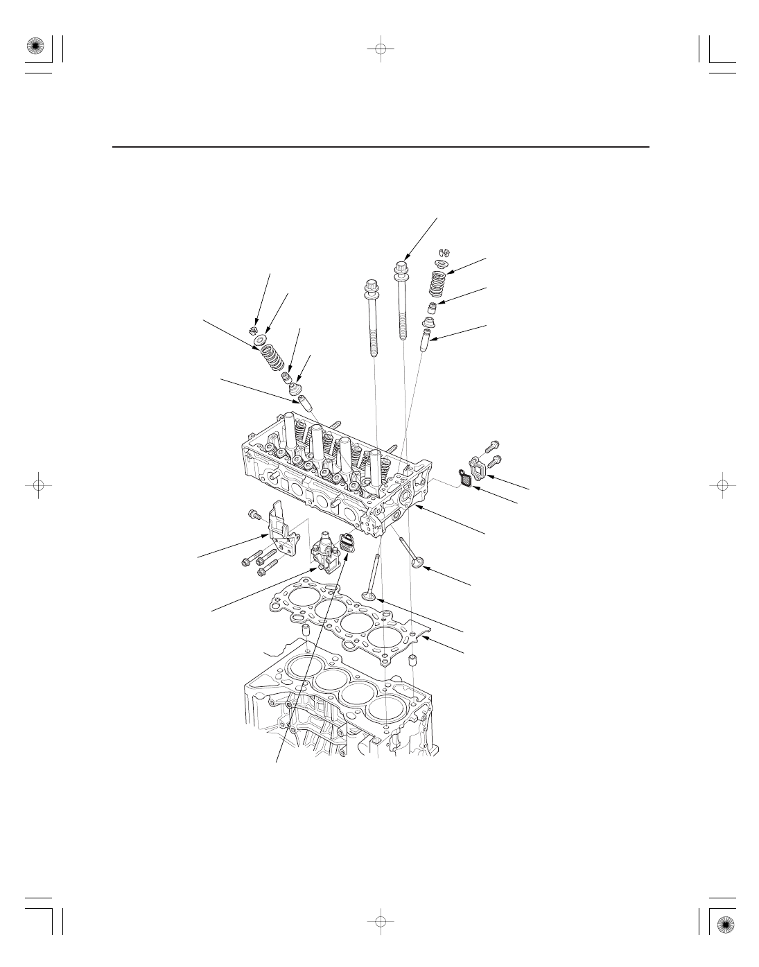
Cylinder Head
CYLINDER HEAD BOLT
INTAKE VALVE SPRING
INTAKE VALVE SEAL
INTAKE VALVE GUIDE
VTC STRAINER
VTC FILTER
CYLINDER HEAD
EXHAUST VALVE
INTAKE VALVE
CYLINDER HEAD GASKET
ROCKER ARM OIL CONTROL
SOLENOID FILTER
EXHAUST VALVE
SEAL
EXHAUST VALVE SPRING
SPRING RETAINER
VALVE COTTERS
VALVE SPRING
SEAT
EXHAUST VALVE GUIDE
HEAT SHIELD
ROCKER ARM OIL
CONTROL SOLENOID
Inspection, page 6-62
Removal, page 6-54
Installation, page 6-59
Replacement, page 6-56
Removal, page 6-38
Inspection, page 6-43
Installation, page 6-62
Removal, page 6-54
Inspection, page 6-55
Installation, page 6-60