Acura CSX. Manual - part 19
*01
SNR9A00A14100000000EAAT00
4-25
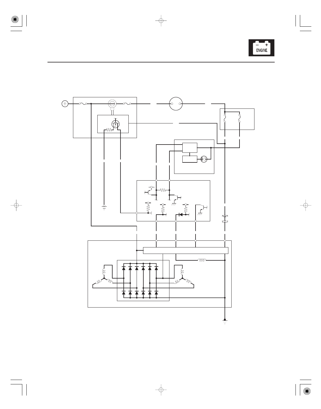
Circuit Diagram
6
3
19
1
F5
17
D2
A3
A2
H1
ELD
CANL
CANH
ALTF
ALTC
ALTL
5 V
ALTERNATOR
DRIVER
YEL
FR
L
C
IG
BRN
ELD
A23
GAUGE CONTROL MODULE (TACH)
IGNITION SWITCH
BAT
IG1
B43
B42
B41
A37
A36
RED
WHT
CPU
YEL
1
BLK/YEL
No. 2 (50 A)
BLK
RECTIFIER
BATTERY
VOLTAGE REGULATOR
2
3
4
B
BLK
G301
UNDER-HOOD FUSE/RELAY BOX
No. 1 (100 A)
ORN
WHT/RED
WHT/GRN
WHT/BLU
UNDER-DASH
FUSE/RELAY BOX
CHARGING
SYSTEM
INDICATOR
IG1 HOT in ON (II)
and START (III)
A1
ECM/PCM
BLU
Q9
WHT
22
17
C101
CANH
CANL
YEL
No. 10
(7.5 A)
No. 3
(10 A)