Lotus Elise / Lotus Exige. Manual - part 104


  Index      Lotus     Lotus Elise / Lotus Exige (engine 1ZZ/2ZZ) - service repair manual 2004 year


Search            


Content   ..  102  103  104  105   ..


Lotus Elise / Lotus Exige. Manual - part 104


Lotus Service Notes                                  Section QH

Page 6

QH.4 - CLUTCH ASSEMBLY

The clutch assembly comprises the friction plate, clutch cover assembly (pressure plate/diaphragm spring/

cover) and release bearing.  For access to the clutch assembly, the engine and transmission must be sepa-
rated.

Removal of clutch assembly:
The transmission may be removed from below:

1.

Remove the LH rear suspension assembly (refer to sub-section DH.3), both driveshaft assemblies (refer
to sub-section FJ.4) and the exhaust system.

2.

Disconnect the clutch release fork, gearchange cables, earth braid and reverse light switch.

3.

The engine must be supported to allow the engine and transmission mountings to be disconnected and
the power unit tilted as necessary to allow the transmission to be withdrawn.  The clutch bell housing is
secured to the engine by 8 bolts as shown overleaf.

4.

Matchmark the clutch cover to the flywheel before progressively loosening each clutch cover bolt half a
turn at a time until clutch cover spring pressure is released.  Withdraw the cover from the flywheel dowels
taking care not to allow the friction plate to drop.

5.

Pull the release fork off the fork pivot ball, and withdraw fork and release bearing from the transmission.

Inspection
1.

Clutch cover:  Check the surface of the pressure plate for scoring or discolouration through overheating.
Check the fingers of the diaphragm spring for excessive wear at the release bearing contact surface.  If
any fingers are indented to a width greater than 6mm, or a depth of 0.5mm, the cover assembly should be
renewed.  If the cover is accidentally dropped, the setting or balance of the assembly could be disturbed.
Replacement of the cover is recommended.

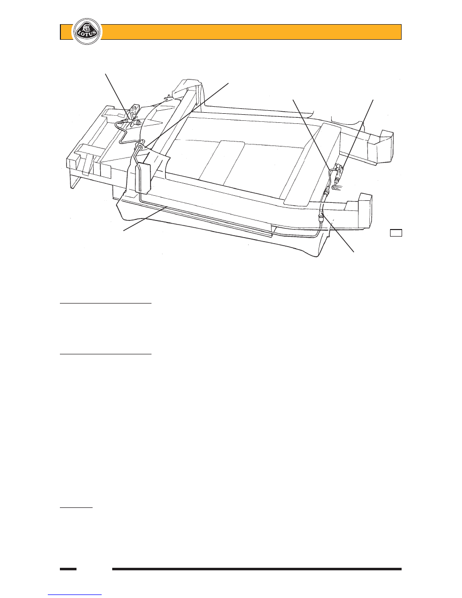
Clutch master cylinder

Dash baffle panel

Steel pipe

Slave cylinder

Steel pipe clipped

        q46a

to heater pipe

Flexible hose
to engine


Lotus Service Notes                                  Section QH

Page 7

2.

Friction plate:  Check the cush drive springs for breakage or cracking of the hub.  Examine the condition
of the friction material for signs of oil contamination, scorching, or any other damage.  Using vernier
callipers, measure the depth of the rivet heads below the surface of the friction material.  Minimum depth:
0.3mm.
With the friction plate mounted on its splines, check the run-out at the outer edge of the friction surface.
Maximum run-out:  0.8mm.
If addressing symptoms of clutch judder, or if any of the above inspections are not passed, renew the
friction plate.

3.

Release bearing: Check the bearing for discernible play, noise or rough feeling, and renew if there is any
doubt.

4.

Flywheel:  Using a dial test indicator, measure the axial run-out at the outer edge of the flywheel drive
surface.
Maximum runout:  0.1mm.
If necessary, renew the flywheel.  When fitting the flywheel:
- progressively tighten the eight fixing bolts in a diametrically opposite sequence, to 49 Nm.
- mark the angular position of each bolt head, and further tighten each bolt in a diagonally opposite
sequence an additional 90°.

Refitting clutch assembly
1.

Using a universal type centralising mandrel, position the friction plate with the 'flatter' side towards the
flywheel, and fit the clutch cover onto the flywheel dowels with the match marks aligned (if applicable).

2.

Fit the clutch cover retaining bolts finger tight and monitor friction plate centralisation as the bolts are
progressively tightened in a diagonally opposite sequence to 19 Nm.

3.

Using a dial test indicator, measure the diaphragm spring tip height variation.  Maximum variation: 0.5mm.
If necessary, use a special clutch tool to achieve the specification.

4.

If the release fork pivot ball had been removed, refit and tighten to 37 Nm.

5.

Apply sparing quantities of Molybdenum Disulphide (MoS

2

) grease to the contact points of the release

fork fingers, release fork pivot, fork retaining spring and pushrod socket.  Also apply sparingly to the
transmission input shaft splines.

6.

Fit the release bearing and fork together, and position in the clutch housing with the fork retained on the
pivot ball by its retaining spring.  Fit the dust boot into the housing aperture.

7.

Refit the engine to the transmission in reverse order to removal, tightening the clutch housing bolts as
follows:
M12 x2;

Upper

64 Nm

M10 x2;

RH side

37 Nm

M10 x2;

Starter Motor

37Nm

M10 x2;

Sump

23 Nm

Illustration overleaf.


Lotus Service Notes                                  Section QH

Page 8

Clutch housing to engine fixings - viewed from gearbox side

M12x55 flange head bolts to block; 64 Nm

M10x65 bolts also secure

M10x55 bolts to

starter motor; 37 Nm

block; 37 Nm

        f134

M10x30 bolts to sump; 23 Nm


Lotus Service Notes                               Section WD

Page 1

AIRBAG SYSTEM

SECTION WD - ELISE NORTH AMERICA

    Sub-Section   Page

General Description

WD.1

3

Airbag Tell Tale

WD.2

3

Data Link Connector

WD.3

3

Trouble Codes

WD.4

4

Lotus Scan Tool

WD.5

4

Safety Precautions, Shipping, Storage & Disposal

WD.6

6

Theory of Operation

WD.7

8

Sensor & Diagnostic Module (SDM)

WD.8

10

Driver Airbag Module

WD.9

10

Rotary Connector

WD.10

11

Passenger Airbag Module

WD.11

13

Seat Belt Pre-tensioners

WD.12

14


Content   ..  102  103  104  105   ..