Lotus Elise / Lotus Exige. Manual - part 56


  Index      Lotus     Lotus Elise / Lotus Exige (engine 1ZZ/2ZZ) - service repair manual 2004 year


Search            


Content   ..  54  55  56  57   ..


Lotus Elise / Lotus Exige. Manual - part 56


   Lotus Service Notes

                Section JJ

Page 7

Tools Required:

Piston Retraction Tool   T000T1242

1.

Remove the rear road wheels.

2.

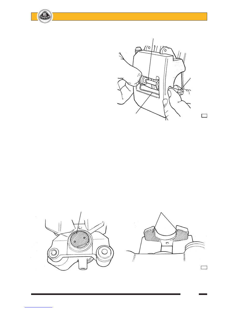
At each rear corner: using a suitable pin
punch, knock the pad retaining pin out
of the calliper towards the outside, tak-
ing precautions as necessary to restrain
the anti-rattle spring from flying off as
the pin is withdrawn.

3.

Remove the anti-rattle spring, and with-
draw both brake pads from the calliper.
Measure the thickness of the lining ma-
terial, and renew the axle set of pads if
any are below 2.5 mm.

4.

Before refitting the pads, inspect the pis-
ton boot for splits, cracks or other dam-
age, and for any signs of fluid leakage
or wetness.
If any such signs are apparent, the complete calliper should be replaced as Brembo do not recommend
that this calliper be dismantled.

5.

If refitting the existing brake pads, refit each pad in the same position as originally fitted.

6.

Before fitting new rear pads, the calliper piston must be screwed back into the calliper down the parking
brake actuation mechanism.  This operation requires the use of special tool T000T1242 and the removal
of the brake disc:
-

Remove the single socket head screw retaining the brake disc, and remove the disc.

-

Fit special tool T000T1242 into the holes in the calliper piston, and screw the piston back down
the parking brake mechanism screwthread until fully bottomed.

-

Refit the brake disc, and tighten the countersunk retaining screw to 12 Nm.

7.

In order to minimise brake squeal from new pads during the bedding-in period, a copper based (PBC)
paste (e.g Renolit) should be used on the pad contact surfaces of the rear callipers in the areas shown:

Pad retaining pin

Retaining
pin snap
ring

       Anti-rattle spring

      j123

Contact face of piston

Calliper outboard fingers

j188


   Lotus Service Notes                                  Section JJ

Page 8

8.

Slide the brake pads into the calliper.  Position the pad anti-rattle spring in the calliper aperture, with the
spring ends located in the recesses provided.  Ensure that the spring is fitted the correct way up, w i t h
the turned spring end in the longer recess.  Press the spring eyes into alignment whilst the pad retaining
pin is inserted through the calliper from the outside.  Ensure that the pin passes through both eyes of the
anti-rattle spring, and both brake pads, and that the pin is fully installed with the snap ring seated in the
outboard side of the calliper.

9.

Refit the roadwheels and press the brake pedal several times to set the brake pad position.  Before
switching on the ignition, check the fluid level in the reservoir and top up if necessary.

10. Ensure the customer is made aware that maximum braking efficiency will be achieved if, for the first few

hundred miles, needless heavy braking is avoided, and the brake pads are allowed to ‘bed in’ fully before
being used to their full potential.

Top surface of bridge including

Bottom surface of bridge

inner surface in contact with

including inner surface

pad backplate

in contact with pad backplate

         j188

Anti-rattle spring

Inboard pad

Turned spring end
in longer recess

Outboard pad

Pad retaining pin

        j124

   Lotus Service Notes

                Section JJ

Page 9

JJ.6 - PARKING BRAKE MECHANISM

Operation of the parking brake lever applies a pull to a short link cable which connects via a horseshoe

compensator to the centre of a single cable linking the two rear callipers.  At each calliper, the cable connects
to a lever which operates the hydraulic piston by mechanical means:

Movement of the calliper lever causes rotation of one of a pair of steel discs, rotation of the other being

restrained by a stop bolt in the cylinder.  Hardened balls housed in ramps machined in the discs, force the discs
apart, and in so doing, apply an axial force to the piston via a screwthread and nut.  The nut is restrained in the
piston by a one way clutch which grips the nut when the parking brake is applied, but  allows it to turn when the
mechanism relaxes, or when the piston is operated hydraulically by the footbrake.  In this way, the mechanical
mechanism is adjusted automatically to compensate for pad wear.

For the auto adjustment system to

function correctly, it is essential that each
calliper parking brake lever is allowed to return
fully when the brake is released, and is not
prevented from doing so by maladjustment of
the parking brake cable.  To check that the
calliper levers are fully returned; with the
parking brake ‘off’, measure the distance
between the cable abutment and calliper lever
as shown.

Needle roller
thrust bearing

Piston
assembly

Driven

Operating

disc

lever

Lever
return
spring

Driving

Return

Stop

Balls

disc

spring

bolt

in ramps

        j126

Calliper park brake lever

  76 mm

Cable abutment

         j139


   Lotus Service Notes                                  Section JJ

Page 10

After verifying this dimension, any slack in the rear cable may be adjusted out at the left hand outer cable

abutment, which is integral with the pivot bracket for the front leg of the lower wishbone.  Remove the engine
bay undertray for access.  After adjustment, re-check the calliper lever ‘off’ dimension.

The parking brake lever is mounted in a steel bracket which also houses the gearchange lever, and is

bolted to the seat mounting crossmember at the front, and to the floor rear crossmember.  The parking brake
lever is secured by two bolts fixing the ratchet quadrant to the bracket.  Access to the lever is available after
removing the cockpit centre trim panel:

LH lower wishbone
front pivot bracket

Horseshoe compensator

Parking brake cable adjuster

         j169

Parking brake lever

Ratchet quadrant

Primary cable

Parking brake tell tale switch

Mounting bracket

Fixing point to
seat rear
crossmember

         j189


Content   ..  54  55  56  57   ..